Table of Contents
Advertisement
Quick Links
Advertisement
Table of Contents

Subscribe to Our Youtube Channel
Related Manuals for BAFANG MM G32.1000


Summary of Contents for BAFANG MM G32.1000
- Page 2 DEALER MAUAL HD DRIVE SYSTEM...
-
Page 3: Table Of Contents
Battery Health Indication Important Notice For your Safety Battery Installation 5 Display (DP C10.UART) Note 1 Drive Unit (MM G32.1000) Specifications and Parameters of the Display Advantages Appearance and Dimensions Scope of Application Function Overview and Key Definations Product Naming Protocol... - Page 4 DEALER MANUAL HD DIRVE SYSTEM...
-
Page 5: Important Notice
IMPORTANT NOT ICE IM PORTANT NOTICE To avoid any harms to riders, before assemble the HD motor you must confirm that the bike frame has high mechanical intensity. The Dealer Manual is to be used by professional e-bike mechanics. Dealers who have not received training on electric bicycle assembly shall not attempt to assemble parts and components by following the Dealer Manual. -
Page 6: For Your Safety
When cabling the product or installing the parts onto the e-bike, be sure to disconnect the battery. BAFANG parts at all times. Serious injury may result if loose or faulty bolts and nuts suddenly come off. Not doing so may result in electric shock. -
Page 7: Note
Do not allow children to play near the product. the official Bafang website: www.szbaf.com. Please consult the nearest dealer for any errors or problems. Do not modify the system. Doing so may lead to malfunction of the system. -
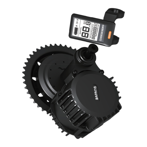
Page 8: Drive Unit (Mm G32.1000)
High starting torque, maximum torque of more than 160 N.m, especially suitable for hill climbing High effciency, low power consumption MM G32.1000 Name of the drive unit Low noise, smooth operation 1501 Date of production, January 2015 in this example; 0001 Production serial number, ran Scope of Application ging from 0000 to 9999;... -
Page 9: Main Techinialc Parameters
DRIVE UNIT(MM G32.1000) Main Technical Parameters Rated voltage (DCV) Rated power (W) 1000 1250 Rated efficiency (%) ≥ 80% Rated rotating speed (rpm) 130~150 Maximum torque (N.m) ≥ 160 Chain wheel Optional chain guard full chain guard / P-shaped chain guard... -
Page 10: Drive Unit Structure And Dimensions
Drive Unit Structure and Dimensions Dimension A 215mm φ210mm(46T) Dimension B Dimension C 123mm Dimension D 68 / 100 / 110 / 120mm Dimension E 175/190/200/210mm Dimension F 50 / 65 / 70 / 75mm Dimension G 88 / 103 / 108 / 113mm DEALER MANUAL HD DRIVE SYSTEM... -
Page 11: System Installation
SYSTEM INSTALLATION 2 SYSTEM INSTALLATION List of Tools to be used Components Use of the Tools Tools Display To tighten M3 & M4 screws Internal hex wrench To fasten M6 & M8 & M33 Internal hexagonal bolts and nutsonto the wrench and two frame adapter and the dedicatd tools... -
Page 12: Component Names
Component Names Drive unit Front chain wheel External speed sensor Battery(Optional) Auxiliary keypad Display DEALER MANUAL HD DRIVE SYSTEM... -
Page 13: Display Installation (Dp C10.Uart)
SYSTEM INSTALLATION Display Installation (DP C10.UART) Rubber clamping ring Left and right display clamps for the φ22.2 handlebar: Left and right display clamps for the φ25.4 handlebar: One or two rubber clamping rings may be needed depending on the diameter of the handlebar (the applicable handlebar specicatons are φ22.2, φ25.4 and φ31.8). -
Page 14: Auxiliary Keypad Installation
Adjust the angle of the display so that you can easily see the display screen when riding. After the angle has been adjusted, tighten the screws to the specified torque. Tightening torque: 1 N.m Auxiliary Keypad Installation keypad clamp Open the auxiliary keypad and assemble it onto a position that is easy for operation. Adjust the angle of the auxiliary keypad to ensure that the keypad is easy to see seen during riding. - Page 15 SYSTEM INSTALLATION hex socket head cap screw M3×8 Fix the keypad onto the handlebar with a screw. Then tighten the fixing screw with an internal hex wrench. Tightening torque:1 N.m female connector at the display male connector at the EB-BUS Match the female connector at the display with the male connector at the EB-BUS as shown in the picture above.
-
Page 16: Battery Rail Installation
Battery Rail Installation Align the mounting holes of the carrier with the mounting holes of the battery rail. Fasten the battery rail onto the battery carrier with hex socket head screws (M5). Tightening torque: 2 N.m Choosing a corresponding battery and under the help of professional mechanics or local dealers to assemble it. External Speed Sensor Installation S R SD02.01 external speed sensor magnet unit... - Page 17 SYSTEM INSTALLATION external speed sensor cable ties If the gap is within the specified range, use the mounting bolt to fix the speed sensor. If the gap is more than 25 mm, please put spacers between the sensor and the chain stay boss to reduce this gap. Tightening torque: 1.5-2 N.m Arrange the speed sensor and the magnet unit as shown in the picture above.
- Page 18 external speed sensor magnet unit spoke Arrange the speed sensor and the magnet unit as shown by the picture above. Mount the magnet unit onto the spoke. Mounting nut of the magnet Tighten up the mounting nut with a straight slot screwdriver. Tightening torque: 1.5-2 N.m DEALER MANUAL HD DRIVE SYSTEM...
-
Page 19: Drive Unit Installation
SYSTEM INSTALLATION Drive Unit Installation battery cable EB-BUS external speed sensor cable Cables should be arranged in advance according to the e-bike type and the cabling system before installing the drive unit. chain wheel 5-M5 screw Assemble the drive unit from right side of bike frame into bottom bracket. Pay attention to the outgoing directions of the cables. - Page 20 Normal Dedicated bottom bracket drive unit Dedicated bottom bracket internal hole, machining it toΦ33.6mm Assemble the drive unit from right side of bike frame into bottom bracket. fixed holder 2-M6 screw M8 screw(dedicated BB) Put the fixed holder on the bottom bracket. Fasten it with M6 screw. Tightening torque: 10 N.m Dedicated: fasten it with M8 screw.
- Page 21 SYSTEM INSTALLATION M33 steel nut Fasten the dedicated M33 steel nut required torque. Tightening torque: 50 N.m M33 aluminum nut Fasten the dedicated M33 aluminum nut tool to required torque. Tightening torque: 25 N.m DEALER MANUAL HD DRIVE SYSTEM...
- Page 22 M8*15 screw L/R crank Assemble the R/L cranks on the main shaft. Lock it with M8 screw. Tightening torque: 35-40 N.m DEALER MANUAL HD DRIVE SYSTEM...
-
Page 23: System Cabling
3 SYSTEM CABLING Connection of the Battery Cable to the Drive Unit female connector for the positive cable at the battery(optional) male connector for the negative cable at the drive unit(optional) The power bus, which is made up of a positive battery cable, a negative battery cable and battery communication cables(optional), is connected to the battery cables at the drive unit. -
Page 24: Connection Of The Eb-Bus To The Drive Unti
SYSTEM CABLING Connection of the EB-BUS to the Drive Unit male connector at the EB-BUS female connector at the drive unit for connection to the EB-BUS Link the EB-BUS cable to the EB-BUS connector at the drive unit. Connection of the Headlight Cable to the Drive Unit(Optional) female connector at the headlight cable male connector for the... -
Page 25: Connection Of The Headlight To The Drive Unit
Connection of the Headlight to the Drive Unit female connector at the headlight cable male connector for the headlight at the drive unit Link the headlight cable to the connector at the drive unit. DEALER MANUAL HD DRIVE SYSTEM... -
Page 26: Battery (Optional)
BATTERY (OPTIONAL) 4 BATTERY (OPTIONAL) Precautions Danger If any liquid leaking from the battery gets into your Do not deform, modify or disassemble the battery. eyes, rinse immediately with clean water (e.g. tap Do not apply solder directly to the battery. Doing so water). -
Page 27: Using The Battery Properly
Using the Battery Charging the Battery Properly When using the battery for the first time, check that the battery has not run low in transport or The battery can be charged at any time no storage. matter how much power is left. However, in the following cases, the battery needs to be If it not intended to use the battery for a long fully charged. -
Page 28: Display (Dp C10.Uart)
6 DISPLAY (DP C10.UART) Specifications and Parameters of the Display 36 V / 48 V Power Supply Rated Current: 10mA Maximum Operating Current: 30mA Power-off Leakage Current: < 1uA Operating Current Supplied to the Controller: 50 mA OperationTemperature: -18~60 % Storage Temperature: -30~ 70 % Waterproof Grade: IP65 Storage Humidity: 30 % -- 70 %... -
Page 29: Function Overview And Key Definations
DISPLAY (DP C10.UART) Function Overview and Key Definitions 6.3.1 Function Overview 6.3.2 Information on the Display Use of a two-way serial communication protocol, simple operation of the display via the external 5-key keypad. Speed display: displaying the real-time speed as SPEED, the maximum speed as MAXS and the average speed as AVG. - Page 30 6.3.3 Key Definitions Distance mode: display of the single-trip distance TRIP and the total distance TOTAL Battery level: 10-segment battery indication; the voltage that each segment represents can be customized down headlight on/off mode DEALER MANUAL HD DRIVE SYSTEM...
-
Page 31: Normal Operation
DISPLAY (DP C10.UART) Normal Operation 6.4.1 On/Off Switch 6.4.3 Switch between Distance Mode and Speed Mode Turn on the device. Press and hold for 2 seconds Briefly press to switch between distance and to power on the display. Press and hold again for speed. - Page 32 6.4.4 Headlight/ Display Backlight 6.4.5 Walk A ssistance Switch Press for 2 seconds. The e-bike enters the walk Press for 2 seconds. The backlight of the display assistance mode, and the symbol WALK is displayed. as well as the headlight and taillight will be turned Once the key is released, the e-bike will exit the on.
-
Page 33: Parameter Setting
DISPLAY (DP C10.UART) 6.4.6 Battery Status Indication When the battery status is normal, a certain number of the battery LCD segments as well as the border light up according to the actual quantity of charge. If all of the 10 segments will black out with the border blinking, the battery needs to be charged immediately. - Page 34 6.5.2 Setting Preparation 6.5.3 Data Reset When the display is active, press twice (interval Press twice (interval < 0.3 seconds) – the < 0.3 seconds). The system will enter the MENU pa- display enters the MENU state. In the speed field , a y is also dis- rameter setting state, in which the display parameters tC is displayed.
- Page 35 DISPLAY (DP C10.UART) 6.5.5 Light Sensitivity 6.5.6 Display Backlight Brightness When the speed field displays bL0, use When the speed field displays bL1, press to choose a figure between 0 and 5. The higher the to choose a figure between 1 and 5. The figure 1 chosen figure, the higher the light sensitivity.
- Page 36 6.5.7 Automatic Off Time 6.5.8 Maintenance Warning (can be deactivated) When the speed field displays OFF,press When the speed field displays nnA, press choose a figure between 1 and 9. The figures indicate to choose either 0 or 1. 0 disables the function w- the minutes that it takes to automatically shut down hile 1 enables it.
- Page 37 DISPLAY (DP C10.UART) 6.5.10 Wheel Diameter Selection battery will flash for 4 seconds, indicating that maintenance is necessary. When the speed position displays Wd, press to select the correct wheel diameter: 16/18/20 The maintenance alert function can be disa- bled: settings maintenance alert (MA) / 22/24/26, 700c, 28/29.
- Page 38 5.5.12 Battery Communication 5.5.11 Speed Limit Setting The speed field displays b01 and the distance field When the speed field displays SPL, the distance fi- displays the speed limit. Press (< 0.3 seconds) eld displays the value of the speed limit. Press to see the other information in sequence.
- Page 39 DISPLAY (DP C10.UART) 5.5.13 Information on the battery menu Information Displayed Explanation in the Speed Field current temperature maximum temperature lowest temperature total voltage current average current remaining capacity full capacity relative state of charge absolute state of charge charge/discharge cycle longest period without charge period since last charge voltage cell 1...
-
Page 40: Error Code Definitions
Error Code Definitions The MAX-C966 display can show e-bike faults. When a fault is detected, the icon will be displayed. In the speed field one of the following error codes will be displayed: Error Code Error Description Error-shooting Method “03” Brake enabled Check whether a brake cable is stuck “04”... -
Page 41: List Of Materials
LIST OF MATERIALS 6 LIST O F MATERIAL S 6.1.1 Normal Bottom Bracket 6.4 Spacer M8*15 Screw Fixed bracket Crank right 2-M6 Screw 5-M5*12 Screw M33 Steel nut Chain wheel Motor M33 Aluminum nut Crank left 35 Spacer 6.1.2 Dedicated Bottom Bracket 6.4 Spacer M8*15 Screw Fixed bracket... -
Page 42: Cables
LIST OF MATERIALS Cables Name Material No. Quantity Specification Integrated cables according to order Speed sensor components according to order Battery cable according to order Headlight cable according to order Taillight cable according to order DEALER MANUAL HD DRIVE SYSTEM... -
Page 43: Service And Warranty Policy
7 SERVICE AND WARRANTY POLICY Suzhou Bafang Motor Science-Technology Co., Ltd BAFANG reserves the right to repair or replace faulty (hereinafter referred to as the BAFANG) guarantees: components, and is only obliged to repair or replace During the warranty period, BAFANG gives warranty them.
Need help?
Do you have a question about the MM G32.1000 and is the answer not in the manual?
Questions and answers