
Related Manuals for BAFANG MM G510.500 18 027


Summary of Contents for BAFANG MM G510.500 18 027
-
Page 1: Table Of Contents
CONTENT MM G510.1000 CONTENT 1 Introduction 2.7 Crank Installation 2.8 External Speed Sensor Installation SR SD02.01 1.1 Advantages 3 Cabling 1.2 Scope of Application 1.3 Product Naming Protocol 3.1 Connection of the Battery Cable to the Drive Unit 3.2 Connection of the Speed Sensor to the Drive Unit 1.4 Drive Unit Appearance 1.5 Drive Unit Structure and Dimensions 3.3 Connection of the EB-BUS to the Drive Unit... -
Page 2: Introduction
1 INTRODUCTION Advantages Product Naming Protocol • Use of torque measurement, pedal-assist speed measurement and wheel-speed mea- There is a badge on the housing, showing infor- surement; the system has a dual feedback mation as follows: protection of the speed signals to ensure safety and reliability of the system G510. -
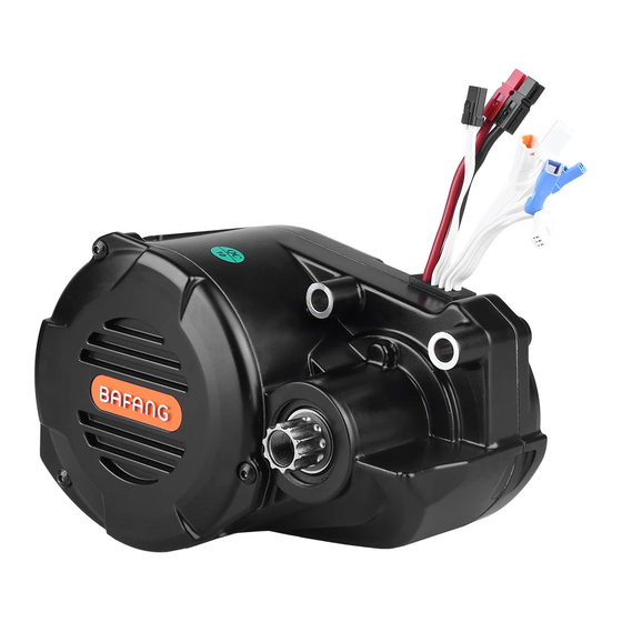
Page 3: Drive Unit Appearance
INTRODUCTION Drive Unit Appearance DEALER MANUAL MM G510.1000... -
Page 4: Drive Unit Structure And Dimensions
Drive Unit Structure and Dimensions DEALER MANUAL MM G510.1000... -
Page 5: Main Technical Parameters
INTRODUCTION Main Technical Parameters Drive unit model MM G510.500 18 027 MM G510.750 12 027 MM G510.1000 12 027 Rated voltage (V) 1000 Rated power (W) Rated efficiency (%) ≥82% ≥82% ≥82% Rated rotating speed 150±10 150±10 150±10 (rpm) Maximum torque (Nm) ≥100... -
Page 6: Installation
2 INSTALLATION List of Tools to be used Use of the Tools Tools To fasten screw onto the frame adapter and the Internal hexagonal wrench drive unit To fasten nuts onto the frame adapter and the Socket spanner drive unit To install chain cover Cross screwdriver To fix and remove the chain wheel lock nut... -
Page 7: Welding Frame Adapter
INSTALLATION Welding Frame Adapter IQC inspection specification for the frame adapter is 53.0 (+0.3/ 0). After welding, the frame adapter need to heat treat together with bicycle frame to ensure the dimension of drive unit installation, the concentricity and the location of mounting hole. - Page 8 M8 dedicated screw stem 1401280000003 M8 flat washer-A level 1401060000196 M8 lock nut 1401080000127 dedicated socket spanner 1) Align the three mounting holes of the drive unit with the mounting holes in the bike frame. From the right of the bike frame, insert the three dedicated M8 screw stem into the three mounting holes in the bike frame and the drive unit, and out from the left.
-
Page 9: Cable Connection
INSTALLATION Cable Connection Connect the connectors of all cables to the connectors of the cables of drive unit (the method of cable arrangement shall be suit for frame adapter. The power bus, which is made up of a positive battery cable, a negative battery cable and battery communication cables (optional), is connected to the battery cables at the drive unit). -
Page 10: Chain Wheel Parts Installation
Chain Wheel Parts Installation chain wheel parts (depend on customer’s requirement) spline nut 1401080000131 dedicated tool Chain wheel installation: align spline teeth of the drive unit with spline teeth on the chain wheel parts and insert chain wheel, use dedicated tool to fasten anticlockwise the spline nut onto the drive unit, tighten torque is 35N.m Crank Installation water-proof M15 in-... -
Page 11: External Speed Sensor Installation Sr Sd02.01
INSTALLATION External Speed Sensor Installation SR SD02.01 external speed sensor magnet unit spoke chain stay Before installing the speed sensor, please make sure the gap between the speed sensor and the magnetic unit is between 5 and 25 mm. Dust cap 2301030000003 mounting bolt M5×12 external speed sensor... - Page 12 Arrange the speed sensor and the magnet unit as shown in the picture above. When installing the magnet unit, make sure its center is aligned with the center of the speed sensor’s induction zone. external speed sensor magnet unit PS01010702/ 2308040000001 spoke Arrange the speed sensor and the magnet unit as shown by the picture above.
- Page 13 INSTALLATION Mounting nut of the magnet PS01010701/ 2327000000003 Tighten up the mounting nut with a straight slot screwdriver. Tightening torque: 1.5 – 2 Nm DEALER MANUAL MM G510.1000...
-
Page 14: Cabling
3 CABLING Connection of the Battery Cable to the Drive Unit female connector for the communication cables at the battery male connector for the communication cables at the drive unit female connector for the positive cable at the battery male connector for the negative cable at the drive unit male connector for the... -
Page 15: Connection Of The Eb-Bus To The Drive Unit
CABLING Connection of the EB-BUS to the Drive Unit male connector at the EB-BUS 2105020000099 female connector at the drive unit for connection to the EB-BUS Link the EB-BUS cable to the EB-BUS connector at the drive unit. Connection of the Headlight Cable to the Drive Unit female connector at the headlight cable male connector for the... -
Page 16: Connection Of The Headlight To The Drive Unit
Connection of the Headlight to the Drive Unit female connector at the headlight cable male connector for the headlight at the drive unit Link the headlight cable to the connector at the drive unit. DEALER MANUAL MM G510.1000... -
Page 17: List Of Materials
LIST OF MATERIALS 4 LIST OF MATERIALS Drive Unit - MM G510.1000 4.1.1 Drive Unit Accessories Name Material No. Quantity Specification M8 nut 1401080000127 M8 bolt 1401280000003 M8 spacer 1401060000196 4.1.2 Motor Cover Accessories Name Material No. Quantity Specification Motor cover 1333000000008 1 cross pan head screw M4×8 1401020000167 3... -
Page 18: Cables
Cables Name Material No. Quantity Specification Integrated cables according to order Speed sensor components according to order Battery cable according to order Headlight cable according to order Taillight cable according to order DEALER MANUAL MM G510.1000... -
Page 19: Service And Warranty Policy
BAFANG • Damage, failure or loss caused by normal wear and tear BAFANG reserves the right to repair or replace faulty components, and is only obliged to repair or replace them. If bike manufacturers or dealers encounter quality issues when using or selling BAFANG products, they can report the purchase order number and serial number of the product to BAFANG service department. -
Page 20: Notes
NOTES NOTES DEALER MANUAL MM G510.1000...
Need help?
Do you have a question about the MM G510.500 18 027 and is the answer not in the manual?
Questions and answers