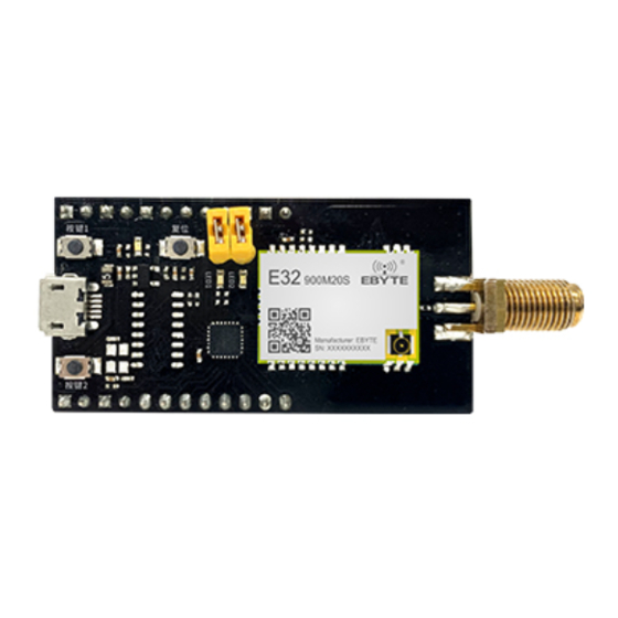
Ebyte MBL Series User Manual
Next generation package-compatible s ub-1gwireless module
Hide thumbs
Also See for MBL Series:
- User manual (17 pages) ,
- User manual (16 pages) ,
- User manual (16 pages)
Summary of Contents for Ebyte MBL Series
- Page 1 MBL Series Evaluation Kit User Manual Next generation package-compatible S ub-1G wireless module E220-400MBL-01...
-
Page 2: Table Of Contents
CHAPTER IV FREQUENTLY ASKED QUESTIONS ..............14 4.1 T ..........................14 HE TRANSMISSION DISTANCE IS NOT IDEAL 4.2 M ..............................14 ODULES ARE EASILY DAMAGED 4.3 T ..............................14 HE BIT ERROR RATE IS TOO HIGH REVISION HISTORY ..........................15 ABOUT US ..............................15 Copyright ©2012–2021,Chengdu Ebyte Electronic Technology Co.,Ltd. -
Page 3: Disclaimer
EBYTE is strictly prohibited. The information contained herein is provided “as is” and EBYTE assumes no liability for the use of the information. No warranty, either express or implied, is given, including but not limited, with respect to the accuracy, correctness, reliability and fitness for a particular purpose of the information. -
Page 4: Chapter 1 Product Overview
1.1 Product Introduction The MBL series evaluation kits are designed to help users quickly evaluate Ebait's next-generation package-compatible wireless modules. Most of the pins on the board are led out to the pin headers on both sides, making it easy for developers to connect a variety of peripherals via jumpers to their needs. -
Page 5: Support Matrix
MCU serial port TXD MCU serial port RXD Module mode switch pin (see module data sheet for details) Bottom plate reference Module mode switch pin (see module data sheet for details) Bottom plate reference 1.3 Support Matrix Copyright ©2012–2021,Chengdu Ebyte Electronic Technology Co.,Ltd. -
Page 6: Chapter 2 Introduction To Software
You can download the sample project from the official website and open the directory as shown in the following figure Table of You can use the IARFor STM8 development environment to locate the entry file to open the contents project description Copyright ©2012–2021,Chengdu Ebyte Electronic Technology Co.,Ltd. - Page 7 Chengdu Ebyte Electronic Technology Co.,Ltd. test board User Manual Copyright ©2012–2021,Chengdu Ebyte Electronic Technology Co.,Ltd.
-
Page 8: Iar Engineering
When switching workspaces, different macro definitions are used, switching the driver files for different modules Changed the Exclude from build property of Drivers/Ebyte/RF to select the target module driver folder to participate in the compilation process. Changed the additional include in the project C/C++ Compiler, which specifies the path to the module driver file. -
Page 9: Main Functions
When calling the transmit function, the underlying driver actually switches the module into standby mode first, usually in this mode to complete the configuration of modulation parameters, such as frequency, power, frequency offset, and so on. After Copyright ©2012–2021,Chengdu Ebyte Electronic Technology Co.,Ltd. - Page 10 When the function is complex, continuous reception or continuous transmission is required, please further switch other modes according to the characteristics of the chip. The timing diagram looks like this: Copyright ©2012–2021,Chengdu Ebyte Electronic Technology Co.,Ltd.
-
Page 11: Programming
It is specially used to bind the user's own sending and receiving logic, abstracted into the output of the "box". Essentially, a module driver is to directly call the user's callback function after determining that the send or receive is complete. As shown in the following Copyright ©2012–2021,Chengdu Ebyte Electronic Technology Co.,Ltd. - Page 12 It is used to connect to a PC for some tests and is generally not required. stm8l15x_it.c All interrupt function entries will be for serial ports, timers, button IO and other interrupt service functions are concentrated here Copyright ©2012–2021,Chengdu Ebyte Electronic Technology Co.,Ltd.
-
Page 13: Chapter 3 Quick Presentation
Chengdu Ebyte Electronic Technology Co.,Ltd. test board User Manual Chapter 3 Quick Presentation 3.1 Signal line connection Matters illustrate Power jumper cap Mode selection jumper auxiliary USB cable, antenna, PC, etc Copyright ©2012–2021,Chengdu Ebyte Electronic Technology Co.,Ltd. -
Page 14: Serial Port Assistant
#RECV identifier, used only as a hint, to represent the data received by the wireless communication module. #SEND identifier, used only for hints, to represent the data sent by the wireless module Serial port data Serial port data transmission directly transmits the required content through XCOM transparent transmission Copyright ©2012–2021,Chengdu Ebyte Electronic Technology Co.,Ltd. -
Page 15: Chapter Iv Frequently Asked Questions
Unsatisfactory power supply may also cause garbled characters, be sure to ensure the reliability of the power supply; Poor or long quality extension wires and feeders can also cause high bit error rates. Copyright ©2012–2021,Chengdu Ebyte Electronic Technology Co.,Ltd. -
Page 16: Revision History
2022-12-29 Modify the schematic diagram of the module and how to use it About us Technical support: support@cdebyte.com Tel:+86-28-61399028 Fax:028- 61543675 Web: https://www.cdebyte.com Address: B5 Mould Park, 199# Xiqu Ave, High-tech District, Sichuan, China Copyright ©2012–2021,Chengdu Ebyte Electronic Technology Co.,Ltd.


