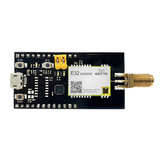
Ebyte MBL Series User Manual
New generation package compatible sub-1g wireless module
Hide thumbs
Also See for MBL Series:
- User manual (17 pages) ,
- User manual (17 pages) ,
- User manual (17 pages)
Summary of Contents for Ebyte MBL Series
- Page 1 MBL Series Evaluation Kit User Manual New Generation Package Compatible Sub-1G Wireless Module E32-900MBL-01...
-
Page 2: Table Of Contents
Ⅳ FREQUENTLY ASKED QUESTIONS ......................14 ............................14 4.1 U NSATISFACTORY TRANSMISSION DISTANCE ..............................14 4.2 M ODULE IS VULNERABLE TO DAMAGE ....................................14 4.3 BER IS TOO HIGH REVISION HISTORY ........................... 15 ABOUT US ..............................15 Copyright ©2012–2021,Chengdu Ebyte Electronic Technology Co.,Ltd. -
Page 3: Disclaimer And Copyright Notice
The contents of this manual are subject to change due to product version upgrade or other reasons.Chengdu Ebyte Electronic Technology Co.,Ltd. reserves the right to make changes to the contents of this manual without any notice or prompting. Chengdu Ebyte Electronic Technology Co.,Ltd. makes every effort to provide accurate information in this manual, but does not warrant that the contents of this manual are error-free, nor do all statements, information and recommendations in this manual constitute any express or implied warranty. -
Page 4: Ⅰproduct Introduction
ⅠProduct Introduction 1.1 Product Description The MBL series evaluation kits are designed to help users quickly evaluate the new generation of package-compatible wireless modules from EBST. Most of the pins on the board are already pinned out to both sides of the row of pins, so developers can easily connect a variety of peripheral devices through jumpers according to their actual needs. -
Page 5: Support List
MCU serial port RXD Module mode switching pins (see module product manual for details) Base plate reference ground Module mode switching pins (see module product manual for details) Base plate reference ground 1.3 Support List Copyright ©2012–2021,Chengdu Ebyte Electronic Technology Co.,Ltd. - Page 6 Silicon Labs E30-400M20S SI4463 Silicon Labs E30-900M20S LLCC68 Semtech E220-400M22S LLCC68 Semtech E220-900M22S SX1278 Semtech E32-400M20S SX1276 Semtech E32-900M20S SX1268 Semtech E22-400M22S SX1262 Semtech E22-900M22S AX5243 ON Semiconductor E31-400M17S LLCC68 Semtech E220-400MM22S LLCC68 Semtech E220-900MM22S Copyright ©2012–2021,Chengdu Ebyte Electronic Technology Co.,Ltd.
-
Page 7: Ⅱ Software Introduction
You can download the sample project from the official website and open the directory as shown below Catalog You can use the IAR For STM8 development environment to find the entry file to open Description the project Copyright ©2012–2021,Chengdu Ebyte Electronic Technology Co.,Ltd. -
Page 8: Iar Engineering
Changed the Exclude from build attribute of Drivers/Ebyte/RF to select the target module driver folder for the compilation process. Changed Additional include in Project C/C++ Compiler, which specifies the module driver file path. Changed Defined symbols in Project C/C++ Compiler to define global macro definitions to help configure module driver properties. -
Page 9: Ending And Eceiving Iming
When the transmit function is called, the underlying driver actually switches the module into standby mode first, where the configuration of modulation parameters, such as frequency, power, frequency bias, etc., is usually done. After the parameters are configured correctly, it gradually enters some intermediate Copyright ©2012–2021,Chengdu Ebyte Electronic Technology Co.,Ltd. - Page 10 When the function is complicated and continuous receiving or continuous transmitting is needed, please further switch to other modes according to the chip characteristics. The timing diagram is shown below. Copyright ©2012–2021,Chengdu Ebyte Electronic Technology Co.,Ltd.
-
Page 11: Programming
It is specifically designed to bind the user's own sending and receiving logic, abstracted as the output of a "box". Essentially, the module driver calls the user's callback function directly after determining whether sending or receiving is complete. Copyright ©2012–2021,Chengdu Ebyte Electronic Technology Co.,Ltd. - Page 12 Used to connect to a PC for some tests, generally not required. stm8l15x_it.c All interrupt functions are entered here, and the interrupt service functions for serial, timer, key IO, etc. are concentrated here. Copyright ©2012–2021,Chengdu Ebyte Electronic Technology Co.,Ltd.
-
Page 13: Ⅲ Quick Demo
Chengdu Ebyte Electronic Technology Co.,Ltd. MBL Evaluation Kit User Manual Ⅲ Quick Demo 3.1 Signal cable connection Matters Description Power Jumper Cap Mode selection jumper cap Assistance USB cable, antenna, PC, etc. Copyright ©2012–2021,Chengdu Ebyte Electronic Technology Co.,Ltd. -
Page 14: Serial Assistant
The #RECV identifier, used only for hints, indicates data received by the wireless example module. The #SEND identifier, used only for hints, indicates data sent by the wireless module Serial Data Transit Serial data pass-through Direct transmission of the required content via Copyright ©2012–2021,Chengdu Ebyte Electronic Technology Co.,Ltd. -
Page 15: Ⅳ Frequently Asked Questions
Poor quality or too long extension cable or feeder line may also cause high BER. Copyright ©2012–2021,Chengdu Ebyte Electronic Technology Co.,Ltd. -
Page 16: Revision History
Modify the module diagram and how to use it 2022-12-29 About us Sales Hotline:4000-330-990 Company Phone:028-61543675 Technical support: support@cdebyte.com Official website: https://www.cdebyte.com Address: Building B5, No.199 West Avenue, High-tech West District, Chengdu, Sichuan Province Copyright ©2012–2021,Chengdu Ebyte Electronic Technology Co.,Ltd.


