Advertisement
Available languages
Available languages
INSTALLATION AND MAINTENANCE INSTRUCTIONS
MI-IM10
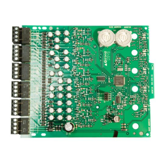
Ten Input Monitor Module
SPECIFICATIONS
Normal Operating Voltage:
Stand-By Current:
Alarm Current:
Temperature Range:
Humidity:
Dimensions:
Accessories:
Wire Gauge:
Maximum SLC Wiring Resistance:
Maximum IDC Wiring Resistance:
Maximum IDC Voltage:
Maximum IDC Current:
BEFORE INSTALLING
This information is included as a quick reference installation
guide. Refer to the appropriate control panel installation manual
for detailed system information. If the modules will be installed in
an existing operational system, inform the operator and local au-
thority that the system will be temporarily out of service. Discon-
nect the power to the control panel before installing the modules.
This system contains static sensitive components. Always ground
yourself with a proper wrist strap before handling any circuits so
that static charges are removed from the body. The housing cabi-
net should be metallic and suitably grounded.
NOTICE: This manual should be left with the owner/user of
this equipment.
GENERAL DESCRIPTION
The MI-IM10 Ten Input Monitor Module is intended for use in an
intelligent alarm system. Each monitor module is intended to inter-
face between a control panel and normally open contact devices,
such as pull stations. A common SLC input is used for all modules,
and the initiating device loops share a common supervisory supply
and ground. Otherwise, each monitor operates independently from
the others. Each module has its own unique address.
A pair of rotary code switches is used to set the address of the
first module from 01 to 90. The remaining modules are automati-
cally assigned to the next nine higher addresses. Provisions are
included for disabling a maximum of two unused modules to re-
lease the addresses to be used elsewhere. Each module also has
panel controlled green LED indicators. The panel can cause the
LEDs to blink, latch on, or latch off.
Included:
(6) 1 × 4 Terminal Blocks
(2) 3.2 cm Stand offs
(4) Screws
(10) 47k Ohm End of Line Resistors
Shipped on Board:
(1) Shunt
M450-02-000
15-32 VDC
3.5 mA
60 mA (assumes all ten LEDs solid on)
–10°C to 55°C
10 to 93% Non-condensing
17.3cm H x 14.7cm W x 3.2cm D
Suitably grounded metallic cabinet
0.9mm2 - 3.25mm2
40 Ohms
40 Ohms
12 VDC
1 mA
COMPATIBILITY REQUIREMENTS
To ensure proper operation, this module shall be connected to a
listed compatible system control panel.
The MI-IM10 Module shall be mounted in a suitably grounded
Metallic Cabinet for EMC compliance.
WIRING
NOTE: All wiring must conform to applicable local codes,
ordinances, and regulations.
1.
Install module wiring in accordance with the job drawings
and appropriate wiring diagrams.
2.
All wiring to the MI-IM10 is done via terminal blocks. In order
to properly make electrical connections strip approximately .6
cm of insulation from the end of wire, sliding the bare end of
the wire under the clamping plate screw.
3.
Set the address on the modules per the job drawing. Use the
rotary code switches to set the address of the first module
(between 01 and 90).
The remaining modules are automatically assigned to the next
nine higher addresses. For example, if the base address switch is
set to 28, the next nine modules will be addressed to 29, 30, 31,
32, 33, 34, 35, 36, and 37.
DO NOT set the lowest address above 90, as the other modules
will be assigned to nonexistent addresses.
4.
A shunt is provided to disable a maximum of two unused
modules. Modules are disabled from the highest address and
work downward. If two modules are disabled, the lowest
eight addresses will be functional, while the highest two will
be disabled. For example, if the shunt for Address Disable is
placed on "two" and the base switch is set to 28, the modules
will be assigned to 28, 29, 30, 31, 32, 33, 34 and 35 while
(2) Nuts
disabling the highest two positions.
NOTE: Place unused shunts on single pin to store on board for
future use.
(3) Small Shunts
C0906-00
1
by Honeywell
Morley IAS Fire Systems
Charles Avenue,
Burgess Hill, West Sussex, RH15 9U
I56-2957-000
Advertisement
Table of Contents

Subscribe to Our Youtube Channel
Related Manuals for Honeywell Morley-IAS MI-IM10


Summary of Contents for Honeywell Morley-IAS MI-IM10
- Page 1 INSTALLATION AND MAINTENANCE INSTRUCTIONS by Honeywell MI-IM10 Morley IAS Fire Systems Ten Input Monitor Module Charles Avenue, Burgess Hill, West Sussex, RH15 9U SPECIFICATIONS Normal Operating Voltage: 15-32 VDC Stand-By Current: 3.5 mA Alarm Current: 60 mA (assumes all ten LEDs solid on) Temperature Range: –10°C to 55°C...
- Page 2 Figure 1. Typical Initiating Device Circuit Configuration: BASE ADDRESS CONNECT MODULES TO 6 7 8 9 6 7 8 9 LISTED COMPATIBLE CONTROL PANELS ONLY RESISTOR CLASS B IDC (TYPICAL) A/B SLCT COM LOSS DISABLE 1 DISABLE 2 POWER LIMITED AND SUPERVISED STATUS FROM PANEL OR...
- Page 3 ISTRUZIONI DI INSTALLAZIONE E MANUTENZIONE by Honeywell MI-IM10 Morley IAS Fire Systems Via Grandi 22 Modulo di ingresso a dieci canali S. Donato Milanese, Milano, Italia SPECIFICHE Normale tensione di esercizio: 15 - 32 VDC Corrente in stand-by: 3.5 mA...
- Page 4 NON impostare l’indirizzo più basso su un valore superiore a 90, poiché agli altri moduli verrebbero assegnati indirizzi inesistenti. Per disabilitare un massimo di tre moduli non utilizzati è disponibile una derivazione. I moduli vengono disabilitati a partire da quello con l’indirizzo più alto e funzionano verso il basso.
- Page 5 INSTRUCCIONES DE INSTALACIÓN Y MANTENIMIENTO by Honeywell MI-IM10 Módulo Monitor Morley IAS Fire Systems C/Ávila 25 con diez circuitos de entrada San Sebastián de los Reyes, 28700 Madrid, Espana ESPECIFICACIONES Tensión de Funcionamiento Normal: 15-32 VDC Corriente en reposo: 3,5 mA Corriente en Alarma: 60 mA (asumiendo que los diez leds están iluminados de forma fija)
- Page 6 NO debe configurar la dirección más baja por encima del número 90, ya que al resto de módulos se les adjudicarían direcciones que no existen. Se proporciona un puente para anular un máximo de dos módulos no utilizados. Estos módulos se anulan empezando por la dirección más alta.
- Page 7 INSTALLATIONS UND WARTUNGSANLEITUNG by Honeywell MI-IM10 Morley IAS Berliner strasse 91 Zehn-Eingangsmodul, überwacht 40880 Ratingen, Germany SPEZIFIKATION Betriebsspannungsbereich: 15-32 VDC Ruhestrom: 3,5 mA Alarmstrom: 60 mA (bei 10 dauerleuchtenden LED) Temperaturbereich: –10°C to 55°C Luftfeuchte: 10 bis 93% ohne Betauung...
- Page 8 Die mitgelieferte Steckbrücke ermöglicht die Abschaltung von max. drei nicht benutzten Modulen. Module werden von der höchsten Adresse aus absteigend abgeschaltet. Wenn zwei Module abgeschaltet werden bleiben die unteren vier Adressen aktiv und die beiden höchsten Adressen werden deaktiviert. Wird die Steckbrücke zur Adressabschaltung z.B. in Position “Zwei”...
Need help?
Do you have a question about the Morley-IAS MI-IM10 and is the answer not in the manual?
Questions and answers