Advertisement
Quick Links
Range locks with a keypad interface are operated by a 4-digit User Code or by an ADA compliant User Key. Manager Keys provide management
access and external power. Programming is accomplished via a Programming Key unique to the lock system.
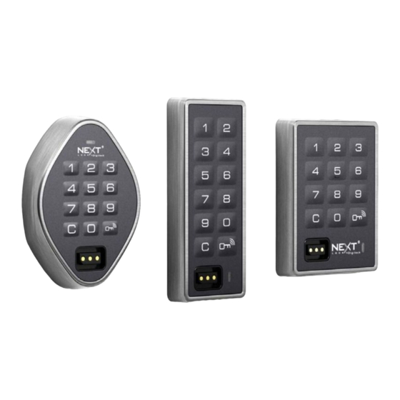
Body Style
Standard
Lock Parts
Front Unit
C Button
Key Slot
Oval
Keys
Operates the lock
Overrides user access
Allows management inspection
Provides external power
Programs Manager Keys
Assigns user credential (in assigned use functionality)
Sets lock functionality
*Up to 25 Manager Keys may be programed to each lock
Key Insertion
NextLock logo must face up.
1
Vertical
Oval
LED Usage Indicator
Shared Use
Assigned Use
Alpha Numeric
Keypad
Key Button
**1 Programming Key allowed per lock group
Product Guide
Keypad Interface
Bolt Mechanism
Range is available in three body styles: Standard, Vertical, and Oval.
Rear Unit
Cover Plate Screw
User Key
Manager Key*
•
Shared & Assigned Use Functionality
Cable
½" (12.7 mm)
Deadbolt
Lock Mounting
Holes
Pin
Cover Plate
Connection Option
Programming Key**
•
•
•
•
•
•
•
•
•
•
•
Advertisement

Related Manuals for Next range

Summary of Contents for Next range
- Page 1 Shared & Assigned Use Functionality Range locks with a keypad interface are operated by a 4-digit User Code or by an ADA compliant User Key. Manager Keys provide management access and external power. Programming is accomplished via a Programming Key unique to the lock system.
-
Page 2: Programming Instructions
Product Guide Keypad Interface Bolt Mechanism Shared & Assigned Use Functionality Setup Locks are shipped with factory default settings (only operates by pressing ). Setup must be completed to program the Programming Key and Manager Keys to all the locks. Insert the Programming Key. - Page 3 Product Guide Keypad Interface Bolt Mechanism Shared & Assigned Use Functionality Programming Instructions Add Manager Keys Manager Keys can be programmed to the locks at any time. Go to a lock requiring additional While the LED is on, insert the Insert each additional Manager Insert the Programming Key.
- Page 4 Product Guide Keypad Interface Bolt Mechanism Shared & Assigned Use Functionality Programming Instructions Set Lock Functionality Each lock can be set for either shared or assigned use functionality. Press to check functionality. If in shared use, LED is red. If in assigned use, LED is green.
- Page 5 Product Guide Keypad Interface Bolt Mechanism Shared & Assigned Use Functionality Set Additional Lock Features (for shared use functionality only) LED Usage Indicator When in shared use functionality, each lock can be programmed to have the LED flash or not flash while the lock is in use. The default setting is ON (red LED flashes while lock is in use).
- Page 6 Product Guide Keypad Interface Bolt Mechanism Shared & Assigned Use Functionality Operating Instructions - In Shared Use Functionality In shared use functionality, users enter a self-selected 4-digit User Code or insert any User Key to lock and the same User Code or User Key to unlock.
- Page 7 Product Guide Keypad Interface Bolt Mechanism Shared & Assigned Use Functionality Operating Instructions - In Assigned Use Functionality In assigned use functionality, users operate the lock with their assigned user credential (either a User Code or a User Key). To reassign a lock to a different user, follow instructions to Assign User Credentials.
-
Page 8: Battery Replacement
Product Guide Keypad Interface Bolt Mechanism Shared & Assigned Use Functionality Support Sleep Mode After three consecutive incorrect User Code entries to unlock, the lock will go into Sleep Mode for one minute. For each subsequent incorrect entry, the lock will remain in Sleep Mode for an additional minute. The keypad is disabled while in Sleep Mode. A valid Manager Key may be used to unlock while the lock is in Sleep Mode.
Need help?
Do you have a question about the range and is the answer not in the manual?
Questions and answers