Table of Contents
Advertisement
SERVICE MANUAL
AIR-CONDITIONER (MULTI TYPE)
<SUPER HEAT RECOVERY MULTI-e>
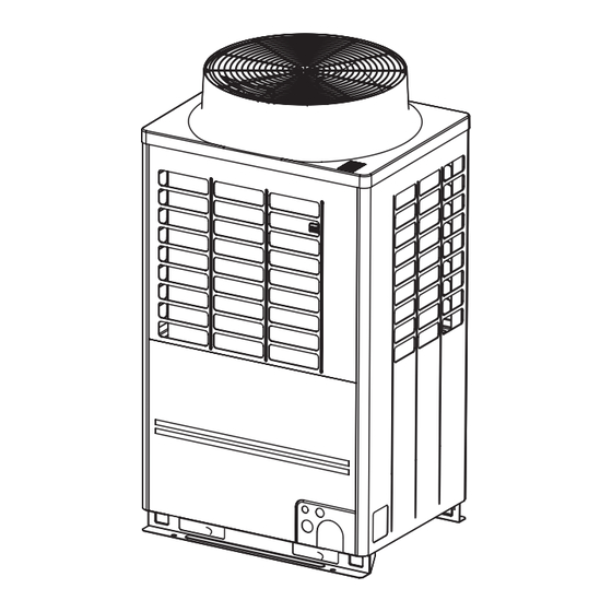
Outdoor Unit
Model name:
MMY-MAP0726FT2P-UL
Flow Selector Unit (FS unit)
Model name:
RBM-Y0383FUL
RBM-Y0613FUL
RBM-Y0963FUL
RBM-Y0384FUL
RBM-Y0614FUL
RBM-Y0964FUL
RBM-Y0611F4PUL
RBM-Y0611F6PUL
FILE NO. SVM-16082-12
Revised on Jan, 2023
Advertisement
Table of Contents
Troubleshooting


Need help?
Do you have a question about the MMY-MAP0726FT2P-UL and is the answer not in the manual?
Questions and answers