Advertisement
Quick Links
Advertisement

Related Manuals for McHale F5000


Summary of Contents for McHale F5000
- Page 1 F5000 Baler Range Re-Assembly Instructions...
- Page 2 Purpose/Scope: Purpose/Scope: F5000 Baler Range Re F5000 Baler Range Re F5000 Baler Range Re F5000 Baler Range Re- - - - Assembly Instructions Assembly Instructions Assembly Instructions Assembly Instructions Only suitably qualified persons experienced in Mechanical assembly and handling, should attempt to take on this task, so it’s achieved in a safe manner.
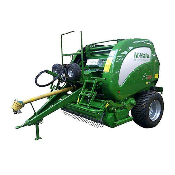
- Page 3 Purpose/Scope: Purpose/Scope: Purpose/Scope: F5000 Baler Range Re F5000 Baler Range Re F5000 Baler Range Re F5000 Baler Range Re- - - - Assembly Instructions Assembly Instructions Assembly Instructions Assembly Instructions Packaged baler as delivered. Re-move all plastic shrink wrap carefully and dispose of responsibly.
- Page 4 Purpose/Scope: Purpose/Scope: Purpose/Scope: F5000 Baler Range Re F5000 Baler Range Re F5000 Baler Range Re F5000 Baler Range Re- - - - Assembly Instructions Assembly Instructions Assembly Instructions Assembly Instructions Using a suitable crane, chains and slings, remove all heavy items as follows.
- Page 5 Purpose/Scope: Purpose/Scope: F5000 Baler Range Re F5000 Baler Range Re F5000 Baler Range Re F5000 Baler Range Re- - - - Assembly Instructions Assembly Instructions Assembly Instructions Assembly Instructions Gently place drawbar on the floor ensuring it is both in the correct position and orientation.
- Page 6 Purpose/Scope: Purpose/Scope: Purpose/Scope: F5000 Baler Range Re F5000 Baler Range Re F5000 Baler Range Re F5000 Baler Range Re- - - - Assembly Instructions Assembly Instructions Assembly Instructions Assembly Instructions Open box with spare parts. Lift crop roller assembly and attach it to the pick-up reel.
- Page 7 Purpose/Scope: Purpose/Scope: Purpose/Scope: F5000 Baler Range Re F5000 Baler Range Re F5000 Baler Range Re F5000 Baler Range Re- - - - Assembly Instructions Assembly Instructions Assembly Instructions Assembly Instructions There are two options for the drawbar: 1. Low drawbar.
- Page 8 Purpose/Scope: Purpose/Scope: Purpose/Scope: Purpose/Scope: F5000 Baler Range Re F5000 Baler Range Re- - - - Assembly Instructions F5000 Baler Range Re F5000 Baler Range Re Assembly Instructions Assembly Instructions Assembly Instructions Drawbar configuration The closest value of H can be selected from table below to determine the most suitable bolt hole position for B, depending on whether low or high drawbar set-up.
- Page 9 Purpose/Scope: Purpose/Scope: Purpose/Scope: F5000 Baler Range Re F5000 Baler Range Re F5000 Baler Range Re F5000 Baler Range Re- - - - Assembly Instructions Assembly Instructions Assembly Instructions Assembly Instructions Option 1: Low drawbar setting Using a crane along with chains...
- Page 10 Purpose/Scope: Purpose/Scope: Purpose/Scope: F5000 Baler Range Re F5000 Baler Range Re F5000 Baler Range Re F5000 Baler Range Re- - - - Assembly Instructions Assembly Instructions Assembly Instructions Assembly Instructions Attach M16 safety bolt, washers and nyloc nut as illustrated.
- Page 11 Purpose/Scope: Purpose/Scope: Purpose/Scope: F5000 Baler Range Re F5000 Baler Range Re F5000 Baler Range Re F5000 Baler Range Re- - - - Assembly Instructions Assembly Instructions Assembly Instructions Assembly Instructions Fit the drawbar stand and hitch eye as illustrated. Ensure there is two washers one on each side of the drawbar stand.
- Page 12 Purpose/Scope: Purpose/Scope: Purpose/Scope: F5000 Baler Range Re F5000 Baler Range Re F5000 Baler Range Re F5000 Baler Range Re- - - - Assembly Instructions Assembly Instructions Assembly Instructions Assembly Instructions With the drawbar mounted correctly and the machine sitting level, adjust hitch eye...
- Page 13 Purpose/Scope: Purpose/Scope: Purpose/Scope: F5000 Baler Range Re F5000 Baler Range Re F5000 Baler Range Re F5000 Baler Range Re- - - - Assembly Instructions Assembly Instructions Assembly Instructions Assembly Instructions Ensure that drawbar stand moves freely. Secure stand in position with hitch pin and lynch pin as illustrated.
- Page 14 Purpose/Scope: Purpose/Scope: Purpose/Scope: F5000 Baler Range Re F5000 Baler Range Re F5000 Baler Range Re F5000 Baler Range Re- - - - Assembly Instructions Assembly Instructions Assembly Instructions Assembly Instructions Then tighten the M16 safety 195 Nm bolts and torque to 195 Nm.
- Page 15 Purpose/Scope: Purpose/Scope: Purpose/Scope: F5000 Baler Range Re F5000 Baler Range Re F5000 Baler Range Re F5000 Baler Range Re- - - - Assembly Instructions Assembly Instructions Assembly Instructions Assembly Instructions Option 2: High drawbar setting Using a crane along with chains or slings,...
- Page 16 Purpose/Scope: Purpose/Scope: Purpose/Scope: F5000 Baler Range Re F5000 Baler Range Re F5000 Baler Range Re F5000 Baler Range Re- - - - Assembly Instructions Assembly Instructions Assembly Instructions Assembly Instructions Remove M24x180 bolt and hitch eye, then slacken M16x170 bolt as shown and fit PTO support chain plate.
- Page 17 Purpose/Scope: Purpose/Scope: Purpose/Scope: F5000 Baler Range Re F5000 Baler Range Re F5000 Baler Range Re F5000 Baler Range Re- - - - Assembly Instructions Assembly Instructions Assembly Instructions Assembly Instructions Remove plastic caps from gearbox. Attach the PTO guard plate...
- Page 18 Purpose/Scope: Purpose/Scope: Purpose/Scope: F5000 Baler Range Re F5000 Baler Range Re F5000 Baler Range Re F5000 Baler Range Re- - - - Assembly Instructions Assembly Instructions Assembly Instructions Assembly Instructions Attach PTO shaft to the gearbox and once aligned with slots, reposition safety bolt and tighten securely.
- Page 19 Purpose/Scope: Purpose/Scope: Purpose/Scope: F5000 Baler Range Re F5000 Baler Range Re F5000 Baler Range Re F5000 Baler Range Re- - - - Assembly Instructions Assembly Instructions Assembly Instructions Assembly Instructions Secure steps with setscrews, washers and nuts provided. 10mm washers Make sure 10mm flat washers are positioned as shown.
- Page 20 Purpose/Scope: Purpose/Scope: Purpose/Scope: F5000 Baler Range Re F5000 Baler Range Re F5000 Baler Range Re F5000 Baler Range Re- - - - Assembly Instructions Assembly Instructions Assembly Instructions Assembly Instructions Attach chain guard and secure it with M8 setscrew and washer.
- Page 21 Purpose/Scope: Purpose/Scope: Purpose/Scope: Purpose/Scope: F5000 Baler Range Re F5000 Baler Range Re- - - - Assembly Instructions F5000 Baler Range Re F5000 Baler Range Re Assembly Instructions Assembly Instructions Assembly Instructions Attach pick-up reel wheel assemblies to the pick-up reel as illustrated.
- Page 22 Purpose/Scope: Purpose/Scope: Purpose/Scope: F5000 Baler Range Re F5000 Baler Range Re F5000 Baler Range Re F5000 Baler Range Re- - - - Assembly Instructions Assembly Instructions Assembly Instructions Assembly Instructions Attach gas struts to the door panels as illustrated. Secure gas struts with M8 nyloc nuts.
- Page 23 Purpose/Scope: Purpose/Scope: Purpose/Scope: Purpose/Scope: F5000 Baler Range Re F5000 Baler Range Re F5000 Baler Range Re F5000 Baler Range Re- - - - Assembly Instructions Assembly Instructions Assembly Instructions Assembly Instructions Remove setscrews from gearbox. Lower platform. Before lowering platform fully on gearbox, secure hoses with clamp as illustrated.
- Page 24 Purpose/Scope: Purpose/Scope: Purpose/Scope: F5000 Baler Range Re F5000 Baler Range Re F5000 Baler Range Re F5000 Baler Range Re- - - - Assembly Instructions Assembly Instructions Assembly Instructions Assembly Instructions Ensure that hoses are secured with clamps. Secure both sides of the platform with M10 setscrews and washers.
- Page 25 Purpose/Scope: Purpose/Scope: Purpose/Scope: F5000 Baler Range Re F5000 Baler Range Re F5000 Baler Range Re F5000 Baler Range Re- - - - Assembly Instructions Assembly Instructions Assembly Instructions Assembly Instructions Secure platform to the gearbox with M12 setscrews and flat washers.
- Page 26 Purpose/Scope: Purpose/Scope: Purpose/Scope: F5000 Baler Range Re F5000 Baler Range Re F5000 Baler Range Re F5000 Baler Range Re- - - - Assembly Instructions Assembly Instructions Assembly Instructions Assembly Instructions Place hose tray in correct position as shown. Secure tray with M12 setscrew, flat washers and nyloc nut.
- Page 27 Purpose/Scope: Purpose/Scope: Purpose/Scope: Purpose/Scope: F5000 Baler Range Re F5000 Baler Range Re F5000 Baler Range Re F5000 Baler Range Re- - - - Assembly Instructions Assembly Instructions Assembly Instructions Assembly Instructions Connect lighting loom. Stretch hoses and loom forward. Ensure that hoses do not rub against chamber rollers.
- Page 28 Purpose/Scope: Purpose/Scope: Purpose/Scope: F5000 Baler Range Re F5000 Baler Range Re F5000 Baler Range Re F5000 Baler Range Re- - - - Assembly Instructions Assembly Instructions Assembly Instructions Assembly Instructions Secure hoses, cables and loom with cable ties. NOTE: Adjust loom length.
- Page 29 Purpose/Scope: Purpose/Scope: Purpose/Scope: F5000 Baler Range Re F5000 Baler Range Re F5000 Baler Range Re F5000 Baler Range Re- - - - Assembly Instructions Assembly Instructions Assembly Instructions Assembly Instructions Tighten hose clamps when the platform is lowered into the normal position.
- Page 30 Purpose/Scope: Purpose/Scope: Purpose/Scope: F5000 Baler Range Re F5000 Baler Range Re F5000 Baler Range Re F5000 Baler Range Re- - - - Assembly Instructions Assembly Instructions Assembly Instructions Assembly Instructions Slide in spreader bar as illustrated. Slide in spreader bar as illustrated.
- Page 31 Purpose/Scope: Purpose/Scope: Purpose/Scope: F5000 Baler Range Re F5000 Baler Range Re F5000 Baler Range Re F5000 Baler Range Re- - - - Assembly Instructions Assembly Instructions Assembly Instructions Assembly Instructions Re-attach net knife trip motor assembly to the netter. NOTE: This applies to F5600 baler only.
- Page 32 Purpose/Scope: Purpose/Scope: Purpose/Scope: F5000 Baler Range Re F5000 Baler Range Re F5000 Baler Range Re F5000 Baler Range Re- - - - Assembly Instructions Assembly Instructions Assembly Instructions Assembly Instructions Attach brackets as illustrated. Secure brackets with M8 setscrews, washers and nuts provided.
- Page 33 Purpose/Scope: Purpose/Scope: Purpose/Scope: F5000 Baler Range Re F5000 Baler Range Re F5000 Baler Range Re F5000 Baler Range Re- - - - Assembly Instructions Assembly Instructions Assembly Instructions Assembly Instructions Open control box and remove control unit. NOTE: Not all models need control unit to open chamber.
- Page 34 Purpose/Scope: Purpose/Scope: Purpose/Scope: Purpose/Scope: F5000 Baler Range Re F5000 Baler Range Re- - - - Assembly Instructions F5000 Baler Range Re F5000 Baler Range Re Assembly Instructions Assembly Instructions Assembly Instructions Open chamber slowly as wheels may become loose and fall out.
- Page 35 Purpose/Scope: Purpose/Scope: Purpose/Scope: F5000 Baler Range Re F5000 Baler Range Re F5000 Baler Range Re F5000 Baler Range Re- - - - Assembly Instructions Assembly Instructions Assembly Instructions Assembly Instructions Secure wheels with linchpins. Remove brackets from axle. Attach bale dropper sensor to the bracket (F5600 only).
- Page 36 Purpose/Scope: Purpose/Scope: F5000 Baler Range Re F5000 Baler Range Re F5000 Baler Range Re F5000 Baler Range Re- - - - Assembly Instructions Assembly Instructions Assembly Instructions Assembly Instructions Ensure sensor is adjusted so it does not protrude past housing as shown.
- Page 37 Purpose/Scope: Purpose/Scope: Purpose/Scope: F5000 Baler Range Re F5000 Baler Range Re F5000 Baler Range Re F5000 Baler Range Re- - - - Assembly Instructions Assembly Instructions Assembly Instructions Assembly Instructions Re-attach bolt to the plate. Ensure bale damper is positioned centrally on axle as shown.
- Page 38 Purpose/Scope: Purpose/Scope: Purpose/Scope: F5000 Baler Range Re F5000 Baler Range Re F5000 Baler Range Re F5000 Baler Range Re- - - - Assembly Instructions Assembly Instructions Assembly Instructions Assembly Instructions M12 bolt Attach spring assembly to the brackets as illustrated.
- Page 39 Purpose/Scope: Purpose/Scope: Purpose/Scope: F5000 Baler Range Re F5000 Baler Range Re F5000 Baler Range Re F5000 Baler Range Re- - - - Assembly Instructions Assembly Instructions Assembly Instructions Assembly Instructions Close chamber door. Disconnect machine from the power pack or tractor.
- Page 40 Purpose/Scope: Purpose/Scope: F5000 Baler Range Re F5000 Baler Range Re F5000 Baler Range Re F5000 Baler Range Re- - - - Assembly Instructions Assembly Instructions Assembly Instructions Assembly Instructions Baler can be jacked up instead of lifting it with crane.
- Page 41 Purpose/Scope: Purpose/Scope: Purpose/Scope: F5000 Baler Range Re F5000 Baler Range Re F5000 Baler Range Re F5000 Baler Range Re- - - - Assembly Instructions Assembly Instructions Assembly Instructions Assembly Instructions Attach wheels. Each wheel has a decal with arrow showing direction of rotation.
- Page 42 Purpose/Scope: Purpose/Scope: Purpose/Scope: F5000 Baler Range Re F5000 Baler Range Re F5000 Baler Range Re F5000 Baler Range Re- - - - Assembly Instructions Assembly Instructions Assembly Instructions Assembly Instructions Ensure that pick-up reel hydraulic hoses are routed well clear of tyres on both sides of machine.
- Page 43 Purpose/Scope: Purpose/Scope: Purpose/Scope: F5000 Baler Range Re F5000 Baler Range Re F5000 Baler Range Re F5000 Baler Range Re- - - - Assembly Instructions Assembly Instructions Assembly Instructions Assembly Instructions The operator’s manual is located in the manual compartment, inside the side panel, as shown.
Need help?
Do you have a question about the F5000 and is the answer not in the manual?
Questions and answers