Advertisement
Available languages
Available languages
Quick Links
Advertisement

Related Manuals for MTD 490-241-B032


Summary of Contents for MTD 490-241-B032
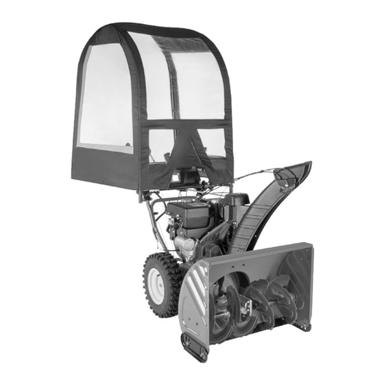
- Page 1 ASSEMBLY INSTRUCTIONS DELUXE UNIVERSAL SNOW THROWER CAB 490-241-B032 769-11609...
- Page 2 PARTS IDENTIFICATION PAGE 710-0909A 710-04468 710-1842A 736-0119 736-0451 1/4"‐20 x 0.375" Socket Hex Set 5/16" Lock Washer 5/16"-18 x 1.75" Hex Bolt (Qty 16) Washer .32 x .93 x .06 Screw – Locking 1/4"‐20 x 0.50" Hex (Qty 16) (Qty 10) (Qty 4) Bolt (Qty 2) 712-0267...
-
Page 3: Tools Required
Tools Required: 3/8, " 9/16" and 1/2" box wrenches (not included); Allen 3/8" 1/2" 9/16" wrench (included). CAUTION: WEARING SAFETY GLASSES IS RECOMMENDED DURING ASSEMBLY. Assistance from another person is recommended for certain steps. Refer to parts identification sheet to ensure you have all necessary parts. Assembly Instructions: 1. - Page 4 5. Insert poles G, narrow end up, into A end of both A/B assemblies. Insert set screw (S) into top of bars A, securing in finger-tight. Front Back 6. Place curved bar C on flat surface, nuts facing up. Insert the labeled end of curved bar D into C (making sure arrows meet).
- Page 5 NOTE: For steps 9, 10 & 11, please be sure you wear safety glasses. Safety Glasses NOTE: You should have four H rods and one I rod. Pull the cover out of box and locate the inside sleeves. Insert the steel collar ends of these H rods into the tops of poles F.
- Page 6 12. Your clamps can be partially pre-assembled. Lower Handle Bars Upper Handle Bars (Horizontal Tube Mount) (Vertical Tube Mount) The clamp assembly that mount to your unit may be oriented horizontally or vertically. The preferred orientation of the clamp assembly is to have the saddles perpendicular to one another.
- Page 7 16. Take pre-assembled K, L & M clamp assemblies. Mount assemblies K & L in the determined location on unit. Use plates M and large bolts N, lock washer T and nuts R to secure K, L & M assemblies to unit. Now tighten small bolt P so both clamp assemblies extend equal distance from frame.
- Page 8 18. Fully insert the ends of the front of the cab assembly into the ends of the assembly (J). Insert set screws (S) into ends of assembly (J). With assistant holding cab assembly horizontal to the ground, tighten all bolts and set screws. CAUTION: Do not overtighten the set screws.
- Page 9 Manual furnished with the product, and has not been subject to misuse, including a dealer or retailer, with respect to any product, shall bind MTD. During abuse, commercial use, neglect, accident, improper maintenance, alteration,...
-
Page 10: Instructions D'assemblage
INSTRUCTIONS D’ASSEMBLAGE CABINE UNIVERSELLE DE LUXE POUR SOUFFLEUSE À NEIGE 490-241-B032 769-11609... - Page 11 PAGE D'IDENTIFICATION DES PIÈCES 710-0909A 710-1842A 710-04468 736-0119 736-0451 Vis de réglage de 1/4"‐20 x 0,375" Boulon hex GR5 de 5/16"-18 x 1,75" (Qté 16) Boulon hex GR5 de (Qté 10) Rondelle de Rondelle de 712-0267 1/4"‐20 x 0,50" (Qté 2) 0,32 x 0,93 x 0,06 (Qté...
- Page 12 Outils requis : Clés polygonales de 3/8," 9/16" et 1/2" (non fournies); 3/8" 1/2" 9/16" une clé Allen (fournie). ATTENTION : IL EST RECOMMANDÉ DE PORTER DES LUNETTES DE PROTECTION DURANT L'ASSEMBLAGE. Il est aussi recommandé de demander l'assistance d'une deuxième personne pour effectuer certaines étapes. Référez-vous à...
- Page 13 5. Insérez les barres G, avec les extrémités étroites vers le haut, dans les extrémités A des ensembles A/B. Insérez les vis de réglage (S) dans les extrémités des barres A, puis serrez les Avant vis à la main. Arrière 6.
- Page 14 NOTE : Portez des lunettes de protection pour effectuer les étapes 9, 10 et 11. Lunettes de protection NOTE : Vous devez avoir cinq tiges flexibles : quatre tiges H et une tige I. Retirez la toile de protection de la boîte et repérez les manches intérieures.
- Page 15 Installation sur le support Installation sur le support 12. Les supports peuvent avoir été assemblés. horizontal des poignées vertical des poignées (assemblés de façon horizontale) (assemblés de façon verticale) Les supports peuvent être assemblés de façon horizontale ou verticale. Il est recommandé d'orienter les supports de façon à ce que les plaques des supports soient perpendiculaires l'une à...
- Page 16 16. Prenez les supports assemblés K/L/M. Installez les supports K/L sur la souffleuse à neige, à l'endroit désiré. Utilisez les plaques M, les boulons larges N, les rondelles de blocage T et les écrous R pour fixer les ensembles K/L/M sur la souffleuse à neige. Serrez maintenant le petit boulon P pour que les deux supports soient à...
- Page 17 18. Insérez à fond les extrémités avant de la cabine dans celles de l'ensemble J. Insérez les vis de réglage (S) dans les extrémités de l'ensemble J. Demandez à une personne de tenir la cabine pendant que vous serrez tous les boulons et toutes les vis de réglage.
- Page 18 NOTES...
- Page 19 NOTES...
- Page 20 MTD LLC, P.O. BOX 361131 CLEVELAND, OHIO 44136-0019; Téléphone : 1 800 800-7310, 1 330 220-4683 MTD Canada Limited - KITCHENER, ON N2G 4J1; Téléphone : 1 800 668-1238...
Need help?
Do you have a question about the 490-241-B032 and is the answer not in the manual?
Questions and answers