Table of Contents
Advertisement
Quick Links
DEA 300
Digital Input and Output Modules
700-321-1BL00/-1BH02/-1BH50/-7BH01/-1EL00/-1FH00
700-322-1BL00/-1BH01/-1BF01
700-322-1HF10/-1HF20/-1HF30/-1HF01/-1HH01
700-323-1BL00/-BH01
700-370-0AA01/-0AL01
Manual
Version 12: 05-12-2016
Manual Order Number: 900-321-1GB11/en
Helmholz GmbH & Co. KG | Hannberger Weg 2 | D-91091 Großenseebach
Phone: +49 9135 7380-0 | Fax: +49 9135 7380-110 | E-Mail: info@helmholz.de | Internet: www.helmholz.com
Advertisement
Table of Contents

Related Manuals for Helmholz DEA 300 Series


Summary of Contents for Helmholz DEA 300 Series
- Page 1 700-321-1BL00/-1BH02/-1BH50/-7BH01/-1EL00/-1FH00 700-322-1BL00/-1BH01/-1BF01 700-322-1HF10/-1HF20/-1HF30/-1HF01/-1HH01 700-323-1BL00/-BH01 700-370-0AA01/-0AL01 Manual Version 12: 05-12-2016 Manual Order Number: 900-321-1GB11/en Helmholz GmbH & Co. KG | Hannberger Weg 2 | D-91091 Großenseebach Phone: +49 9135 7380-0 | Fax: +49 9135 7380-110 | E-Mail: info@helmholz.de | Internet: www.helmholz.com...
- Page 3 (photocopy, microfilm, or other method) without the express written permission of Helmholz GmbH & Co. KG, not even for use as training material, or using electronic systems. All rights reserved in the case of a patent grant or registration of a utility model or design.
- Page 4 Revision history of this document: Edition Date Revision New module 700-332-1HF30 DO 16 x Rel. DC60V/0.5 A bistable 12.12.2011 added. Updated version. Module 700-332-1HF30 DO 16 x Rel. DC60V/0.5 A bistable 08.11.2013 chapter 4.5.5.1 Parameterising and 4.5.5.2 Aktivating the relays added.
-
Page 5: Table Of Contents
Contents Safety Information General Restriction of access Information for the user Use as intended Avoiding use not as intended! Installation and mounting Mounting Foreword Restriction of access Planning assembly Minimum clearance Mounting of the modules on the DIN rail Wiring Protection from external electric interference Current consumption and power loss Mounting isolated modules... - Page 6 4.2.5 DEA DI 32 x 120 V AC 4.2.6 DEA DI 16 x 120/230 V AC Digital output modules 4.3.1 DEA DO 32 x 24 V DC/0.5 A 4.3.2 DEA DO 16 x 24 V DC/0.5 A 4.3.3 DEA DO 8 x 24 V DC/2.0 A Digital input/output modules 4.4.1 DEA DI 16/DO 16 x 24 V DC/0.5 A...
-
Page 7: Safety Information
Safety Information Please observe the safety information given for your own and other people's safety. The safety information indicates possible hazards and provides information about how you can avoid hazards. The following symbols are used in this manual. Caution, indicates hazards and sources of error gives information hazard, general or specific danger of electric shock... -
Page 8: Restriction Of Access
The DEA 300 module is exclusively for use with an S7-300 particular application. programmable controller from Siemens or with a PAS 153 PROFIBUS Slave Interface from Helmholz. DEA 300 modules are only used as part of a complete system. For that reason, the configuring engineer, user, and installing technician must observe the standards, safety, and accident prevention rules applicable in the particular application. -
Page 9: Installation And Mounting
Installation and mounting Installation and mounting must be effected in compliance with VDE 0100 IEC 364. Because it is an IP20 (OPEN type) module, you must Before you start install it in a (switching) cabinet. installation work, all system components must be disconnected from their power source. -
Page 10: Mounting
Mounting Foreword This section describes planning of mechanical assembly, preparation of components for mounting, and final mounting itself. Restriction of access The DEA 300 module must be installed according to VDE 0100 IEC 364. The modules are open equipment and must only be Only authorized persons installed in electrical equipment rooms, cabinets, or housings. -
Page 11: Minimum Clearance
Minimum clearance Minimum clearances must be observed because • it ensures cooling of the DEA 300 modules • it provides space to insert and remove modules Non-observance of the • it provides space to route cables minimum distances can destroy the module at •... - Page 12 Fig. 2-3: Plugging in bus connectors Hook on the modules (1), slide them up to the left module (2), and click them downward (3). Fig. 2-4: Using modules Screw the modules on with a torque of 0.8 to 1.1 Nm. Fig.
-
Page 13: Wiring
Wiring Protection from external electric interference On all systems and plants in which the DEA 300 modules are installed, it is important to ensure that the system or plant is connected to a protective ground conductor to remove electromagnetic interference. Makes sure that all supply, signal, and bus cables are correctly installed and that cable routing is correct. -
Page 14: Outdoor Cable Laying
Fig. 3-1: Potentials in an isolated module assembly Outdoor cable laying • The same guidelines apply as for indoor cable laying. • The cables must be laid on metal cable trays. Lighting protection must always be based on an • Joints between cable trays must be conductively connected. individual assessment of •... - Page 15 Fig. 3-2: Relay contact for EMERG. OFF in the output circuit DC-operated solenoids must be connected with diodes or Zener diodes. Fig. 3-3: Relay with snubber element AC-operated solenoids are operated with Varistors or RC elements. Fig. 3-4: Relay with snubber element DEA 300...
-
Page 16: Wiring The Dea 300 Front Connector
20-way front connector with spring-type terminal: Order No 700-392-1BJ01 40-way front connector with EasyConnect ® Order No 700-392-1AM10 Fig. 3-5: Helmholz 20- and 40- way front connector 3.6.1 Wire 40-way connector with screw-type terminal Technical specifications Order number 700-392-1AM01 Number of terminals... -
Page 17: Wire 20-Way Connector With Screw-Type Terminal
• With the cables brought out from the module at the bottom, start with terminal 40 or 20 and then proceed wiring alternately, in the sequence of order terminal 39, 19, 38, 18 etc. • With the cables brought out from the module at the top, start with terminal 1 or 21 and then proceed wiring alternately in the sequence of order terminal 2, 22, 3, 23, etc. - Page 18 • Open the DEA 300 modules (1). • Snap the front connector into the signal module (2) Fig. 3-7: Bringing the front connector into the wiring position • Strip the isolation from the cables. • When using connector sleeves, crimp the sleeves with the cables. •...
-
Page 19: Wire 40-Way Connector With Spring Contacts
3.6.3 Wire 40-way connector with spring contacts Technical specifications Order number 700-392-1BM01 Number of terminals Terminal type spring contacts Connectable cables flexible, fixed Cross-section with/without end ferrules 0,34 – 1,5 mm² Strip-back length 8 mm Weight Approx. 70 g Easy wiring of front connector with spring contacts: put a screwdriver (for slotted grub screws 0,6 x 3,5) vertically into the The unlock mechanism of the front connector... -
Page 20: Wire 20-Way Connector With Spring Contacts
3.6.4 Wire 20-way connector with spring contacts Technical specifications Order number 700-392-1BJ01 Number of terminals Terminal type spring contacts Connectable cables flexible, fixed Cross-section with/without end ferrules 0,34 – 1,5 mm² Strip-back length 8 mm Weight Approx. 50 g Easy wiring of front connector with spring contacts: put a screwdriver (for slotted grub screws 0,6 x 3,5) vertically into the chamber with the green unlock mechanism until mechanical stop, The unlock mechanism... -
Page 21: Wire 40-Way Connector With Easyconnect
3.6.5 Wire 40-way connector with EasyConnect ® clamp connection technique Technical specifications Order number 700-392-1AM10 Number of terminals Terminal type Spring Connectable cables Flexible cables Cross-section without end ferrules 0.34 – 1 mm² Strip-back length 8 – 10 mm Wire end ferrules Not required Open terminal 180°... -
Page 22: Digital Modules
Digital Modules Foreword Different digital modules are available for connection of sensors and encoders and/or loads and actuators. This section provides the technical data of the digital modules. It also provides information about features, exceptions, module view, and block diagrams of the digital modules. Digital input modules The following digital input modules are described in this section: •... - Page 23 Fig. 4-1: View of module and block diagram of DI 32 x 24 V DC Technical data Order number 700-321-1BL00 Number of inputs Isolation (from backplane bus) yes (via optocoupler) in groups of Input voltage • nominal value DC 24 V •...
-
Page 24: Dea Di 16 X 24 V Dc
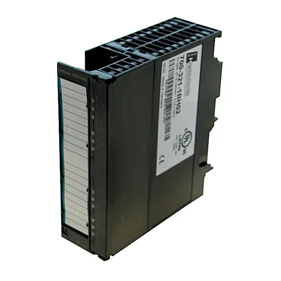
Weight 260 g Dimensions W x H x D [mm] 40 x 125 x 117 Front connector 40-way 4.2.2 DEA DI 16 x 24 V DC Order number: 700-321-1BH02 The DI 16 x 24 V DC has the following features: •... -
Page 25: Dea Di 16 X 24 V Dc Source Input
Delay time typ.1.2 ... 4.8 ms Connection of 2-wire initiator • permissible quiescent current for signal "0" max. 1.5 mA Cable length unshielded max. 600 m Cable length shielded max. 1000 m Current consumption internal typ. 20 mA • external max. -
Page 26: Dea Di 16 X 24 V Dc With Hardware And Diagnostic Interrupts
Technical data Order number 700-321-1BH50 Number of inputs Isolation (from backplane bus) yes (via optocoupler) in groups of Input voltage, reference potential L+ nominal value 24 V DC • • for signal "0" +30 ... -5 V • for signal "1" -13 ... - Page 27 • Programmable diagnostic interrupt • Programmable hardware interrupt • Programmable input delays Fig. 4-4 shows the block diagram of the DEA DI 16 x 24 VDC with hardware and diagnostic interrupts, followed by the technical data. Fig. 4-4: View of module and block diagram of DI 16 x 24 V DC with hardware and diagnostic...
- Page 28 Sensor power supplies (Vs) Green LED per output • Monitoring of Wire-break yes, at I < 1 mA Power rated voltage of the DC 24 V electronics and encoder L+ Sensor Power Supply Outputs • Number of outputs Output voltage with load min.
- Page 29 4.2.4.1 Parameterising the module Use STEP 7 to parameterise the digital module for 16 x 24 V DC with process and diagnostic interrupts. The parameterisation must be performed with the CPU in the STOP condition. Once all parameters are defined, they can be loaded from the PG (programming device) into the CPU.
- Page 30 4.2.4.5 Parameterisable and non-parameterisable diagnostic messages Parameterisable and non-parameterisable diagnostic messages A distinction is made between parameterisable and non- parameterisable diagnostic messages. Parameterisable diagnostic messages are only available if diagnosis has been enabled by way of parameterisation. The parameterisation is performed in the parameter block "Diagnosis" in STEP 7. The non-parameterisable diagnostic messages are always provided by the digital module, irrespective of whether or not diagnostics are enabled.
- Page 31 Reading out diagnostic messages The individual diagnostic messages can be read out in detail using SFCs in the user program. The corresponding error causes can be displayed in the module diagnostics of STEP 7 (see STEP 7 online help). Display of diagnostic messages via the SF LED Errors on digital modules which are capable of performing self- diagnostics are displayed using the SF LED (group error LED).
- Page 32 Assignment of the encoder supplies to the channel groups The two encoder supplies for the module serve as the power supplies for two channel groups: • Inputs 0 to 7; • Inputs 8 to 15. The diagnosis for this encoder supply is also parameterised in these channel groups.
- Page 33 4.2.4.7 Behavior and Diagnostics of the Module 700-321-7BH01 DI 16 x DC 24 V Effect of operating and mode supply voltage on the input values The input values of the Module 700-321-7BH01 DI 1 x DC 24 V depend on the operating mode of the CPU and on the supply voltage of the module.
- Page 34 Failure of the supply voltage with redundant encoder incoming supply If an external redundant power supply is provided for the encoder supply (Vs), no failure of the encoder supply is signalled in case of Note failure of the supply voltage L+. However, a failure of the internal and/or external auxiliary voltage and/or a tripped fuse will be signalled.
- Page 35 4.2.4.9 Interrupts of the Module 700-321-7BH01 DI 16 x DC 24 V The interrupts are divided into: • Diagnostic interrupt • Hardware interrupt Enabling interrupts The interrupts are not preset – in other words, they are inhibited without appropriate parameter assignment. Assign parameters to the Interrupt Enable in STEP 7 Diagnostic interrupt If diagnostic interrupts are enabled, then active error events (initial...
-
Page 36: Dea Di 32 X 120 V Ac
Interrupt-triggering channels The channel triggered by the hardware interrupt is entered in the start information of the OB 40 in the OB40_POINT_ADDR variable. Fig. 4-7 shows the assignment of the bits to the local data double word 8. Byte Variable Data type Description OB40_MDL_ADDR... - Page 37 Fig. 4-8 shows the block diagram of the DEA DI 16/DO 16 x 24 V DC/0.5 A, followed by the technical data. Fig. 4-8: View of module and block diagram of DI 32 x 120 V Fig. 4-9: Module view of DI 32 x 120 V AC DEA 300...
- Page 38 Technical specifications Order number 700-321-1EL00 Number of outputs Isolation from backplane bus Yes (optocoupler) in groups of Input voltage nominal value 120 V AC • • for signal "0" 0 ... 20 V • for signal "1" 74 ... 132 V Frequency range 47 …...
-
Page 39: Dea Di 16 X 120/230 V Ac
4.2.6 DEA DI 16 x 120/230 V AC Order number: 700-321-1FH00 The DI 16 x 120/230 V AC has the following features: • 16 inputs, isolated in 4 groups of 4 inputs, isolated from the backplane bus in 4 groups •... - Page 40 Fig. 4-10: View of module and block diagram of DI 16 x 120/230 V AC Fig. 4-11: Module view of DI 16 x 120/230 V AC DEA 300...
- Page 41 Technical specifications Order number 700-321-1FH00 Number of outputs Isolation from backplane bus Yes (optocoupler) in groups of Input voltage nominal value 120/230 VAC • all load voltages must be of the same phase • for signal "0" 0 ... 40 V for signal "1"...
-
Page 42: Digital Output Modules
Digital output modules This section describes the following digital output modules: • 700-322-1BL00 DO 32 x 24 V DC /0.5 A • 700-322-1BH01 DO 16 x 24 V DC /0.5 A 4.3.1 DEA DO 32 x 24 V DC/0.5 A Order number: 700-322-1BL00 The DO 32 x 24 V DC/0.5 A has the following features: •... - Page 43 Technical data Order number 700-322-1BL00 Number of outputs Isolation (from backplane bus) yes (via optocoupler) in groups of Supply voltage U nominal value DC 24 V • • ripple V max. 3.6 V • permissible range (with ripple) 20 ... 30 V value at 1 <...
-
Page 44: Dea Do 16 X 24 V Dc/0.5 A
4.3.2 DEA DO 16 x 24 V DC/0.5 A Order number: 700-322-1BH01 The DO 16 x 24 V DC/0.5 A has the following features: • 16 outputs, isolated from the backplane bus • Output current 0.5 A • Nominal output voltage DC 24 V •... - Page 45 Technical data Order number 700-322-1BH01 Number of outputs Isolation (from backplane bus) yes (via optocoupler) in groups of Supply voltage U nominal value DC 24 V • • ripple V max. 3.6 V • permissible range (with ripple) 20 ... 30 V value at 1 <...
-
Page 46: Dea Do 8 X 24 V Dc/2.0 A
4.3.3 DEA DO 8 x 24 V DC/2.0 A Order number: 700-322-1BF01 The DO 8 x 24 V DC/2.0 A has the following features: • 8 outputs, isolated from the backplane bus • Output current 2.0 A • Nominal output voltage 24 V DC •... - Page 47 Technical data Order number 700-322-1BF01 Number of Outputs Isolation (from backplane bus) yes (via optocoupler) in groups of Supply voltage U nominal value DC 24 V • • ripple V max. 3.6 V • permissible range (with ripple) 20 ... 30 V Short circuit protection electronic Short circuit current - switched-mode...
-
Page 48: Digital Input/Output Modules
Digital input/output modules This section describes the following digital input/output modules: • 700-323-1BL00 DI 16/DO 16 x 24 V DC / 0.5 A • 700-323-1BH01 DI 8/DO 8 x 24 V DC / 0.5 A 4.4.1 DEA DI 16/DO 16 x 24 V DC/0.5 A Order number: 700-323-1BL00 The DI 16/DO 16 x 24 V DC/0.5 A has the following features: •... - Page 49 Technical data Order number 700-323-1BL00 Number of inputs Isolation (from backplane bus) yes (via optocoupler) in groups of Input voltage nominal value DC 24 V • • for signal "0" -3 ... +5 V • for signal "1" +13 ... +30 V Input current •...
-
Page 50: Dea Di 8/Do 8 X 24 V Dc/0.5 A
4.4.2 DEA DI 8/DO 8 x 24 V DC/0.5 A Order number: 700-323-1BH01 The DI 8/DO 8 x 24 V DC/0.5 A has the following features: • 8 inputs, isolated from the backplane bus • 8 outputs, isolated from the backplane bus •... - Page 51 Technical data Order number 700-323-1BH01 Number of inputs Isolation (from backplane bus) yes (via optocoupler) in groups of Input voltage nominal value DC 24 V • • for signal "0" -3 ... +5 V • for signal "1" +13 ... +30 V Input current •...
-
Page 52: Relay Output Modules
Relay output modules This section deals with the following relay output modules: • 700-322-1HF10 8 outputs relay 5 A • 700-322-1HF20 8 outputs relay 5 A with suppressor • 700-322-1HH01 16 outputs relay 2 A • 700-322-1HF01 8 outputs relay 2 A •... - Page 53 Technical specifications Order number 700-322-1HF10 Number of outputs Isolation from backplane bus Yes (optocoupler) Supply voltage of the relays L+ DC 24 V Contact voltages DC 24 to 120 V AC 48 to 230 V Continuous thermal current 5 A per group Horizontal mounting up to +30 °C max.
- Page 54 Permissible potential difference between GND and supply voltage of the DC 75 V/ AC 60 V • internal relays between GND or supply voltage of the AC 250 V • internal relays and the outputs • between the outputs of different groups AC 500 V Insulation test between GND...
- Page 55 Lamp load AC 230 V Power Number of switching cycles Typical value 1000 W 25,000 1500 W 10,000 10 ∗ 58 W 25,000 Low-energy lamps/ fluorescent lamps with electronic ballast 1 ∗ 58 W 25,000 Fluorescent lamps with conventional correction 10 ∗...
-
Page 56: Dea Do 8 X Rel. 230 V Ac/5 A With Suppressor
4.5.2 DEA DO 8 x Rel. 230 V AC/5 A with suppressor Order number: 700-322-1HF20 The DO 8 x rel. 230 V AC/5 A with suppressor has the following properties: • 8 outputs, floating in groups of 1 • Load voltage DC 24 V to 120 V; AC 24 V to 230 V •... - Page 57 Technical specifications Order number 700-322-1HF20 Number of outputs Isolation from backplane bus Yes (optocoupler) Supply voltage of the relays L+ DC 24 V Contact voltages DC 24 to 120 V AC 48 to 230 V Continuous thermal current 5 A per group Relay contact life can be Horizontal mounting up to +30 °C max.
- Page 58 Dimensions W x H x D [mm] 40 x 125 x 120 Weight approx. 360 g Front connector 40-way Permissible potential difference • between GND and supply voltage of the DC 75 V / AC 60 V internal relays between GND or supply voltage of the AC 250 V •...
- Page 59 AC 120 V 3.0 A 2.0 A 1.0 A 0.5 A AC 230 V 3.0 A 2.0 A 1.0 A 0.5 A Lamp load AC 230 V Power Number of switching cycles Typical value 1000 W 25,000 1500 W 10,000 10 ∗...
-
Page 60: Dea Do 16 X Rel. 230 V Ac/2 A
4.5.3 DEA DO 16 x Rel. 230 V AC/2 A Order number: 700-322-1HH01 The DO 16 x rel. 230 V AC/2 A has the following properties: • 16 Outputs, floating in groups of 2 • Load voltage DC 24 V to 120 V; AC 48 V to 230 V •... - Page 61 Technical specifications Order number 700-322-1HH01 Number of outputs Isolation from backplane bus Yes (optocoupler) Supply voltage of the relays L+ DC 24 V Contact voltages DC 24 to 120 V AC 48 to 230 V Continuous thermal current max. 2 A per output max.
- Page 62 Permissible potential difference between GND and supply voltage of the DC 75 V / AC 60 V • internal relays between GND or supply voltage of the AC 230 V • internal relays and the outputs • between the outputs of different groups AC 500 V Insulation test between GND...
-
Page 63: Dea Do 8 X Rel. 230 V Ac/2 A
4.5.4 DEA DO 8 x Rel. 230 V AC/2 A Order number: 700-322-1HF01 The DO 8 x rel. 230 V AC/2 A has the following properties: • 8 Outputs, floating in groups of 2 • Load voltage DC 24 V to 120 V; AC 48 V to 230 V •... - Page 64 Continuous thermal current max. 3 A per output max. 4 A per group Operation of a digital input Possible Short-circuit current acc. to IEC 947-5-1 with cos ϕ 1.0: 600 A circuit-breaker with characteristic B cos ϕ 0.5...0.7: 900 A with fuse Diazed 8 A: 1000 A...
- Page 65 Make/break capacity and life of contacts Number of switching Voltage/current cycles, typical value [mill.] Relay contact life can be for ohmic load • extended using an external DC 24 V 2.0 A suppressor circuit. 1.0 A 0.5 A DC 60 V 0.5 A DC 120 V 0.2 A AC 48 V...
-
Page 66: Dea Do 16 X Rel. Dc 60 V/0.5 A Bistable
4.5.5 DEA DO 16 x Rel. DC 60 V/0.5 A bistable Order number 700-322-1HF30 The DO 16 x Rel. DC 60 V/0.5 A bistable has the following features: o 16 outputs, isolated in groups of 1 or more o Load voltage DC to 60V, AC to 50 V o suitable for AC/DC solenoid valves, contactors, motor starters, low-power motors and signal lamps o the last switch state is preserved in the event of a failure... - Page 67 Fig. 4-21: Assembly view and block diagram of the DO 16 x Rel. DC 60 V/0.5 A bistable DEA 300...
- Page 68 Technical data Order number 700-322-1HF30 Number of outputs Isolation from backplane bus yes (via optocoupler) Relay supply voltage L+ 24 V DC Switching voltage DC to 60 V max. AC to 50 V max. Continuous thermal current max. 0.5 A per output can be used to control digital inputs Short circuit current per IEC 947-5-1 with line...
- Page 69 Rated potential difference between M and relay supply voltage DC 75 V / AC 60 V • intern between M or relay supply voltage and the AC 1000 V • intern outputs • between outputs in different groups AC 1000 V Switching capacity and lifetime of contacts Number of switching voltage/current...
- Page 70 Relays and Their Corresponding Control Bits Relay Byte of Outputs Bit ON Bit OFF DEA 300...
- Page 71 Control Bits for Relays 0 through 7 on the Variable Table Control Bits for Relays 8 through 15 on the Variable Table DEA 300...
-
Page 72: Other Modules
Other modules 4.6.1 Dummy Module DM 370 Order number: 700-370-0AA01 20-pin 700-370-0AL01 40-pin The dummy module DM 370 reserves a slot for a module not parameterised. It can be used as a dummy for: • interface modules, without reserving address space •... - Page 73 Fig. 4-22: Module view of the dummy module front connector 20-way Fig. 4-23: Module view of the dummy module front connector 40-way DEA 300...
- Page 74 Technical specifications Order number Front connector 20-way 700-370-0AA01 Front connector 40-way 700-370-0AL01 Current consumption (from backplane bus) ca. 5 mA Power loss typ. 0.03 W Dimensions W x H x D [mm] 40 x 125 x 117 Weight ca. 180 g surrounding air temperature 0 °C to +60 °C •...
- Page 75 For reasons of downwards compatibility, If any 8-bit module is however, new CPUs are still also able to use the 8-bit method. used, all 9-bit modules Systeme Helmholz modules generally use the more reliable 9-bit connected to the transmission method. backplane bus will revert to using the 8-bit There are, however, modules that only use the 8-bit method.
-
Page 76: Ordering Data
Ordering data Helmholz Order No. Sectional rail Sectional rail length 160 mm 700-390-1AB60 Sectional rail length 482 mm 700-390-1AE80 Sectional rail length 530 mm 700-390-1AF30 Sectional rail length 830 mm 700-390-1AJ30 Sectional rail length 2000 mm 700-390-1BC00 Front connector 40-way front connector with screw-type...
Need help?
Do you have a question about the DEA 300 Series and is the answer not in the manual?
Questions and answers