Table of Contents
Advertisement
Quick Links
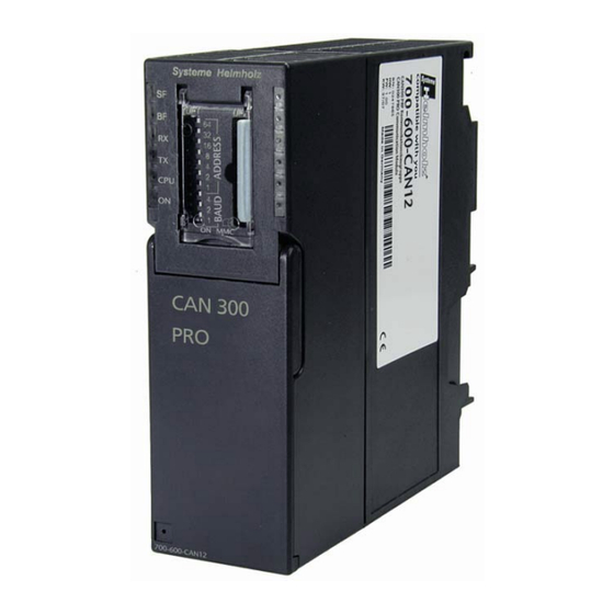
CAN 300 PRO
CAN Communication Module for S7-300
CANopen® Master, CAN Layer 2 or SAE J1939
700-600-CAN12
Manual
Edition 3 / 06.07.2009 / HW30 & FW1.08 and higher
Order number of manual: 900-600-CAN12/en
Systeme Helmholz GmbH
Hannberger Weg 2
D-91091 Großenseebach
Phone: +49 9135 7380-0
Fax: +49 9135 7380-110
E-mail: info@helmholz.de
Internet: www.helmholz.de
Advertisement
Table of Contents

Related Manuals for Helmholz CAN 300 PRO


Summary of Contents for Helmholz CAN 300 PRO
- Page 1 CAN 300 PRO CAN Communication Module for S7-300 CANopen® Master, CAN Layer 2 or SAE J1939 700-600-CAN12 Manual Edition 3 / 06.07.2009 / HW30 & FW1.08 and higher Order number of manual: 900-600-CAN12/en Systeme Helmholz GmbH Hannberger Weg 2 D-91091 Großenseebach...
- Page 3 (photocopy, microfilm, or other method) without the express written permission of Systeme Helmholz GmbH, not even for use as training material, or using electronic systems. All rights reserved in the case of a patent grant or registration of a utility model or design.
- Page 4 Revision history of this document: Edition Date Revision 11.03.2009 version minor corrections Behavior of the power LED in the CANopen® Master mode 02.07.2009 Correction of the calling parameter of the FCs Addition of the CANopen® Tools of the CANParam v4.10...
-
Page 5: Table Of Contents
Process image in the PLC Byte 0: Module status Byte 1: Error status (EFLG) of the CAN controller 21 Byte 2: FIFO status bits Byte 3/4: CAN controller Tx/Rx error counter ® Byte 5: CANopen master status CAN 300 PRO... - Page 6 Layer 2 debug display 6.7.2 CANopen Debug display ® CANopen Tools 6.8.1 Scan Slaves 6.8.2 SDO Transmission 6.8.3 Slave Mapping Programming in the PLC Overview Layer 2 handling blocks 7.2.1 General 7.2.2 FC 65 CANSEND 7.2.3 FC 66 CANRCV CAN 300 PRO...
- Page 7 7.9.1 General 7.9.2 FC 70 CANSEND_SAE_J1939 7.9.3 FC 71 CANRCV_SAE_J1939 Return parameter RETVAL Upgrading from CAN 300 to CAN 300 PRO 83 Differences between CAN 300 and CAN 300 PRO 83 Layer 2 SAE J1939 ® CANopen CAN 300 PRO...
- Page 8 Appendix 10.1 Technical Data 10.2 Pin assignment 10.3 Further Documentation Notes CAN 300 PRO...
-
Page 9: Safety Information
Hazard, general or specific Danger of electric shock General The CAN 300 PRO module is only used as part of a complete system. The operator of a machine system is responsible for observing all safety and accident prevention regulations applicable to the application in question. -
Page 10: Restriction Of Access
It provides the installing technician with all the necessary data. The CAN 300 PRO module is exclusively for use in a S7-300 programmable controller from Siemens. For that reason, the configuring engineer, user, and installing technician must observe the standards, safety and accident prevention rules applicable in the particular application. -
Page 11: Installation And Mounting
Installation and Mounting The CAN 300 PRO module must be installed according to VDE 0100 IEC 364. Because it is an “OPEN type” module, you must install it in a (switching) cabinet. Ambient temperature: 0 ºC – 60 ºC. Before you start installation work, all system components must be disconnected from their power source. -
Page 12: Minimum Clearance
Minimum clearance Minimum clearances must be observed because it ensures cooling of the CAN 300 PRO modules it provides space to insert and remove modules it provides space to route cables it increases the mounting height of the module rack to 185 mm,... - Page 13 Hook on the modules (1), slide them up to the left module, and click them downward (3). Screw the modules on with a torque of 0.8 to 1.1 Nm. CAN 300 PRO...
-
Page 14: System Overview
300 PRO module does not have an integrated terminating resistor. No terminating resistor The maximum cable lengths primarily depend on the baudrate is integrated into the used. CAN 300 PRO module. Bit rate Bus length Bit time 1 Mbps 30 m 1 µsec. -
Page 15: Application And Function Description
It can be used both in the central controller and in the expansion rack (e.g. with the IM360, 361, 365). Use of the CAN 300 PRO is also possible in an ET200M (with IM153), but this drastically reduces the performance. -
Page 16: Connections
Connections The CAN 300 PRO module has behind the hinged front cover a 9- way SubD connector for the CAN bus and an USB connector for configuration and diagnostics. Pin assignment: SUBD connector CAN CAN Low A 24V power supply is... -
Page 17: Dip Switch
500K 800K Project memory card MMC The CAN 300 PRO module stores the project in an internal memory (256 KByte). As an option, the project can be stored on an MMC. With the MMC, the valid project can be transferred onto the new module when the module is replaced. -
Page 18: Configuration In The Plc
Configuration in the PLC The CAN 300 PRO module is configured as the CP 340 communication module in the programming software of the PLC. The module can be used wherever a CP module is allowed, i.e. also in the expansion unit after an interface module. - Page 19 Accesses to the input image can only be performed with the I/O direct access commands: L PEB, L PEW, L PED. For CPU 318 the IO-addresses must never address in cyclic memory area. CAN 300 PRO...
-
Page 20: Process Image In The Plc
Bit 0: The CAN 300 PRO module has processed the configuration and is ready for operation. Bit 1: The Bit is always 1 to indicate a CAN 300 PRO module is plugged. Bit 7: Group error bit for errors on the CAN controller, more precise information about the cause of error can be found in byte 1. -
Page 21: Byte 1: Error Status (Eflg) Of The Can Controller
If a CAN frame has been correctly transmitted, the error counter is decremented again. If the counter is greater than 96, the CAN controller goes into “warning” mode (see 5.2). If the error counter exceeds 127, the CAN controller goes into “error passive.” CAN 300 PRO... -
Page 22: Byte 5: Canopen Master Status
Byte 6: Assignment SDO requests (CANopen Master) ® The CAN 300 PRO module can process in CANopen Master mode up to 8 SDO requests at the same time, with 4 request channels being used internally. This byte provides information about the number of currently running SDO requests, both internal requests and those started by the PLC. -
Page 23: Configuration Of The Module
CAN 300 PRO module. Installation of the USB interface driver If this is the first time a CAN 300 PRO module is being connected to the PC, the operating system will try to install a suitable USB driver. This driver provides the interface between the USB interface and the operating system (Windows). - Page 24 • To be able to specify the search path for the driver (generally the CD supplied), it is necessary to make the following setting and confirm it with “Next.” CAN 300 PRO...
- Page 25 “Next” button. • If the CAN CD is in a local drive, the search for the driver now begins. • If the driver is found, a WindowsXP logo compatibility query appears. CAN 300 PRO...
- Page 26 • Confirm with the button “Continue installation.” The driver is then installed. • After successful installation, the operation is completed by clicking the “Finish” button. CAN 300 PRO...
- Page 27 A new COM port has now been added in the device manager. This COM port must be selected in the CANParam software to be able to communicate with the CAN 300 PRO module. CAN 300 PRO...
-
Page 28: Creation Of A Layer 2 Project
New project” function or with the project wizard. The project wizard guides you through the most important settings to obtain a new and complete project. Für die Erstellung von ® CANopen Master Projekten lesen Sie bitte Kapitel 6.4. CAN 300 PRO... -
Page 29: Setting The Can Bus Baudrate
As an alternative, the baudrate can be set using the DIP switch. 6.3.2 Setting the transmission mode type The CAN 300 PRO module supports both the protocol format CAN 2.0A (11 bits) and CAN 2.0 B (29 bits). Mixed operation with 11-bit and 29-bit For use of the SAE J1939 data handling blocks, a CAN 2.0B (29... -
Page 30: Mask Filter
Frames that are received with the IDs set The default setting of there will be passed to the S7 as the next frame bypassing the the acceptance mask (0h normal receive buffer. to 7FFh) is to allow receipt of all frames. CAN 300 PRO... -
Page 31: Bit Filter
CANopen slaves. If the CAN 300 PRO is to be used as a slave station, filtering for all CAN frames for this station can be defined via the node ID setting. The node ID is stored in the lower 7 bits of the CAN ID. -
Page 32: Script Events
(Structure ID, length, data byte 1, data byte 2, etc. ) Fetch Transmit frame with RTR bit 1 Start Start Timer X Stop Stop Timer X Wait Wait X (1..65535) ms Comment line 100 lines per script can be created with the CAN 300 PRO module. CAN 300 PRO... -
Page 33: Timer
1 msec. For the phase 0 msec to 1 msec before the repetition time. If the option “to the PLC” is selected, the frame is transmitted simultaneously on the CAN bus and to the PLC. With this option, the PLC can be synchronized on a CAN frame. CAN 300 PRO... -
Page 34: Synchro Window
For the synchronous window, both Timer1 & 2 must be started window to function correctly, these two timers must be started in directly one after the succession. other in a script! CAN 300 PRO... -
Page 35: Creation Of A Canopen Project
® module can be parameterized as a CANopen Master. ® The CANopen Master in the CAN 300 PRO module works independently of the PLC. 6.4.1 Settings of the master Node ID: The master requires a node ID for broadcasting the master heartbeat. - Page 36 PLC I/O buffer “OUT”: Buffer for transmitting PDOs The buffer size has to fit with the PLC programming to assure correct data transferbetween PLC and CAN 300 PRO module. The information about memory type and base address is to alleviate the mapping of the PDOs between PLC an module.
-
Page 37: Creating A Slave
Consumer heartbeat: The slave monitors the heartbeat of the master. As the monitoring time, the master heartbeat time times 1.5 is used. The object 1016/1 is written during start-up. Active PDOs: Overview of the PDOs defined or used with this slave. CAN 300 PRO... -
Page 38: Setting Tpdos
A PDO frame consists of up to 8 bytes. The data types If the data types are set now have to be assigned from the left/first byte to the last byte of incorrectly, data may be the PDOs used. corrupted! CAN 300 PRO... - Page 39 Byte 8 Unsigned16 Integer32 unused unused The CAN 300 PRO will format the values internally with this information and enter them correctly in the IO buffer for the PLC. The following data types are available: Integer8, integer16, integer32, unsigned8, unsigned16, unsigned32.
-
Page 40: Setting Rpdos
A PDO frame consists of up to 8 bytes. The data types If the data types are set now have to be assigned from the left/first byte to the last byte of incorrectly, data may be corrupted! the PDOs used. CAN 300 PRO... - Page 41 PDOs can be specified directly in addition to the list of data types. If the option is activated, this mapping will be written into the objects 1600 (RPDO 1), 1601 (RPDO 2), 1602 (RPDO 3), and 1603 (RPDO 4) during start-up. CAN 300 PRO...
-
Page 42: Plc I/O Buffer Concept
The ANY pointer information on FB 30 "IO Read" with "I 50.0 BYTE 50" copies the PLC IN buffer into the process image memory from IB50 to IB99: CALL 20 , DB20 Base :=256 Dest :=P#I 50.0 BYTE 50 STAT :=MW20 :=M22.6 RetVal :=MW24 NewData:=M22.0 CAN 300 PRO... - Page 43 Address in PLC unused IB 50 unused IB 51 … … … Node 1: TPDO4 (Byte 0-1) IW 70 Unsigned16 Node 1: TPDO4 (Byte 2-5) ID 72 Unsigned32 unused IB 76 … … … unsued IB 99 CAN 300 PRO...
-
Page 44: Adding Sdos
“Autostart of the slaves”). An error on writing the SDOs does not result in cancellation of slave initialization. The last error to occur can be viewed in the ® CANopen Debug Screen (see Sec. 6.7.2). CAN 300 PRO... -
Page 45: Uploading
Uploading The project currently being worked on can be imported into the CAN 300 PRO module ("upload"). Downloading Project on the module can be loaded into the CANParam software with this function also the processing. Diagnostics/debugging To simplify debugging, you can query the status of the CAN 300 PRO module with menu item "Debug."... - Page 46 The information about CAN bus, to the PLC and internally the buffers and FIFOs are Note: The CAN 300 PRO module has receive and transmit buffers only relevant in layer 2. of 400 frames (low priority) and 20 frames (high priority). The ®...
-
Page 47: Canopen Debug Display
Sec. 7.2.4). ® 6.7.2 CANopen Debug display ® If the CAN 300 PRO module is operated in CANopen Master operation, the status of the master and the livelist can be displayed on the second diagnostics page. ® The CANopen Debug dialog box provides the following... - Page 48 SDO Idx, Sub Idx, SDO Abort Last received SDO abort code Updating of the slave status list can be halted to copy the list into the clipboard. The text can then be copied, for example, into an e-mail or documentation. CAN 300 PRO...
-
Page 49: Canopen Tools
The SDO transmission can be used to read or write the SDO If the data are objects of any slave. This slave must own the behavior of its incorrectly, it does show object. an Error message with the Abort-Code of the slave! CAN 300 PRO... - Page 50 Data. Send SDO: With this button you send the SDO data to the module and therefore to the slave. Replies the slave with an abort, it does show an error message with the Abort-Code from the slave. CAN 300 PRO...
-
Page 51: Slave Mapping
Node ID: Node-ID of the slave, which PDO mapping data will be fetched. Show mapping: If the button pressed the reading of mapping from the slave is started. If at least a mapped PDO is available then it will be displayed on the screen. CAN 300 PRO... -
Page 52: Programming In The Plc
CANopen Master operation. ® Data handling blocks for use of the CAN 300 PRO as a CANopen slave are available on request. The choice of handling blocks and the configuration of the CAN 300 PRO module must match. -
Page 53: Layer 2 Handling Blocks
PLC, and any frames can be If layer 2 data handling blocks are used, the transmitted. CAN 300 PRO module The following FCs are available in layer 2: must also be parameterized with a Transmission of a CAN frame... -
Page 54: Fc 65 Cansend
The FC65 “CANSEND” Parameter STAT contains the status of the CAN 300 PRO module must not be called in OB 1 (cycle) and OB 35 (see Sec. -
Page 55: Fc 66 Canrcv
4 bits (bit 0 to bit 3). Bit 6 is the RTR bit of the CAN frame. If bit 7 is set, the message went via high-priority FIFOs. If the function block has read a frame from the CAN 300 PRO module, bit Recd is set. -
Page 56: Fc 67 Canctrl
6 = Clear all FIFOs on the module 7 = Reset FIFO error bits Parameter STAT contains the status of the CAN 300 PRO module (see Sec. 7.2.5). The parameter is always assigned a value even if no frame has been received. -
Page 57: Parameter Stat
Bit 15 Bit 14 Bit 13 Bit 12 CAN controller Module is group error CAN 300 PRO (always 1) Bit 11 Bit 10 Bit 9 Bit 8 Module running, read-in of the... -
Page 58: Canopen
“SDO response” are available. The object number, access mode, and type are stored in the first 4 bytes of the CAN frame. The last 4 bytes of the CAN frame then contain the value for the SDO. CAN 300 PRO... -
Page 59: Functions
PDO3 (rx) 1000 401h – 47Fh PDO4 (tx) 1001 481h – 4FFh PDO4 (rx) 1010 501h – 57Fh SDO (tx) 1011 581h – 5FFh SDO (rx) 1100 601h – 67Fh NMT Error Control 1110 701h – 77Fh CAN 300 PRO... -
Page 60: Network Management
Each CANopen slave must respond to the nodeguarding frame with a status frame. ® The control can detect failure of a CANopen slave using nodeguarding. [COB-ID: 700h + Node-ID + 1Byte data with status of the slave] CAN 300 PRO... - Page 61 All stations can perform an emergency stop on receiving an emergency frame, for example. BootUp message: ® CANopen slaves generate a BootUp message after switch-on that the master can recognize to initialize this new station. [COB-ID: 700h + node ID + 1 byte data: 00h] CAN 300 PRO...
-
Page 62: Start-Up Behavior Of The Canopen Master
If a slave fails in cyclic operation and the master option “Autostart of the slaves” is active, this slave is automatically re- initialized and started. If the slave is a mandatory device, a master restart is performed and the procedure restarts at step 1. CAN 300 PRO... -
Page 63: Operating Conditions For Canopen Slave Devices
® Operating conditions for CANopen Slave devices ® To be able to use a CANopen Slave on the CAN 300 PRO in ® CANopen master operation, the slave must meet the following conditions: 1. The slave should perform a restart after the NMT reset command. -
Page 64: Tips On Start-Up / Troubleshooting
CANopen debug display/SDO abort code display If these tips do not help, contact our support. Either by phone or at support@helmholz.de. If information about their slave device is also at hand (manual), please also send this information. CAN 300 PRO... -
Page 65: Canopen Data Handling Modules
If the CANopen Master process SDOs, and to perform network management. data handling blocks are These data handling blocks can only be used if the CAN 300 PRO used, the CAN 300 PRO ® module has also been parameterized in CANopen... -
Page 66: Fb 20 Canopen
NewData BOOL M 22.0 Base Address of the CAN 300 PRO module Dest ANY pointer to the target area for the input buffer in the PLC. The data are copied from the module into this area up to the maximum number of bytes specified. -
Page 67: Fb 21 Canopen
M 22.7 RetVal MW 24 Base Address of the CAN 300 PRO module Source ANY pointer to the target area for the output buffer in the PLC. The data are from the PLC into the module, no more than the specified number of bytes. -
Page 68: Fb 22 Canopen
New_Livelist INOUT BOOL M 30.3 Base Address of the CAN 300 PRO module Emergency ANY pointer to 8 bytes memory in which the data of the emergency frame are stored Livelist ANY pointer to the memory in which the data of... - Page 69 Node 2: 05 = operational Node 3: 7E = failed Node 4: 05 = operational Node 7: 05 = operational Failure detection of a slave by the master can only work if the device monitoring has been activated on the slave. CAN 300 PRO...
-
Page 70: Fb 23 Canopen
STAT WORD MW 20 BOOL M 22.7 RetVal MW 24 Base Address of the CAN 300 PRO module Node Node number (1…127) Func Function code: 0 = Resume Node Control 1 = Start Node 2 = Stop Node 3 = Disconnect Node... -
Page 71: Fb 24 Canopen Sdo
M 40.1 INOUT BOOL M 40.7 Done INOUT BOOL M 40.2 Base Address of the CAN 300 PRO module Node Node number (1…127) SDO_Request SDO function: 0 = Reading the SDOs 1 = Writing the SDOs SDO_Index SDO index SDO_SubIndex SDO subindex... - Page 72 SDO: CALL 24 , DB24 Base :=256 Node :=MW41 SDO_Request :=MB43 SDO_Index :=MW44 SDO_Subindex :=MB46 SDO_Response :=MB48 SDO_Abortcode:=MD50 STAT :=MW20 RetVal :=MW54 SDO_Data :=MD56 SDO_DataLen :=MB49 Activate :=M40.0 Busy :=M40.1 :=M40.7 Done :=M40.2 40.1 NEXT 40.2 40.7 CAN 300 PRO...
-
Page 73: Fb 27 Canopen
M 40.1 INOUT BOOL M 40.7 Done INOUT BOOL M 40.2 Base Address of the CAN 300 PRO module Node Node number (1…127) SDO_Request SDO function: 0 = Reading the SDOs 1 = Writing the SDOs SDO_Index SDO index SDO_SubIndex SDO subindex SDO_Data ANY pointer to the data for the SDO;... - Page 74 27 , DB27 Base :=256 Node :=MW41 SDO_Request :=MB43 SDO_Index :=MW44 SDO_Subindex :=MB46 SDO_Data :=P#M 150.0 BYTE 20 SDO_Response :=MB48 SDO_DataLen :=MB49 SDO_Abortcode:=MD50 STAT :=MW20 RetVal :=MW54 Activate :=M40.6 Busy :=M40.1 :=M40.7 Done :=M40.2 40.1 L2RC 40.2 40.7 CAN 300 PRO...
-
Page 75: Fb 25 Canopen
RetVal MW74 Recd INOUT BOOL MW 22.1 Base Address of the CAN 300 PRO module L2Frame Any pointer for the complete layer 2 frame STAT Status of the module, see Section 7.2.5 Error bit is 0 on successful implementation RetVal... -
Page 76: Fb 26 Canopen
7.7.8 FB 26 CANopen PDO resend The CAN 300 PRO uses 4 methods to transmit PDOs to the slave (RPDO of the slave): 1. Transmission on change of the value (event-driven [255]) 2. Transmission on every transfer to the module (event-driven on PLC cycle [254]) 3. -
Page 77: Fb 28 Canopen
® 7.7.9 FB 28 CANopen SYNC trigger After the FB 28 has been called, the CAN 300 PRO module ® transmits a SYNC frame. If, in configured CANopen Slaves, RPDOs of type “SYNC trigger by PLC(0)” are defined, these PDOs are transmitted before the SYNC frame, if the values have changed. -
Page 78: Sdo Abort Codes
0800 0021h Data item cannot be transmitted/stored because of local device control 0800 0022h Data item cannot be transmitted/stored because of device status 0800 0023 h Dynamic generation of the object directory not possible or already exists CAN 300 PRO... -
Page 79: Sae J1939 Communication
Initialization of the module in the start-up OBs is not necessary. The module starts automatically if the PLC is switched to RUN and stops if the PLC goes into the STOP state. Multipacket messages are currently not supported. CAN 300 PRO... -
Page 80: Fc 70 Cansend_Sae_J1939
STAT byte must always be queried before transmission. must not be called in OB 1 (cycle) and OB 35 Parameter STAT contains the status of the CAN 300 PRO module (time OBs) (see Sec. 7.2.5). The parameter is always assigned value, even if simultaneously or mixed! the Snd bit is not set. -
Page 81: Fc 71 Canrcv_Sae_J1939
As the passed parameter, the base address of the module must be passed as an integer number (Base). If the function block has read a frame from the CAN 300 PRO module, bit Recd is set. Parameter STAT contains the status of the CAN 300 module (see Sec. -
Page 82: Return Parameter Retval
Slave is still in cyclic bootup 80F8: SDO data block pointer to small for SDO-data 80FA: Abortcode received from SDO-job 81E1: Node number not valid (1..127) 82E2: Function code not valid 82E3: PDO number not valid (1..4) CAN 300 PRO... -
Page 83: Upgrading From Can 300 To Can 300 Pro
Upgrading from CAN 300 to CAN 300 PRO If projects have so far been performed with the old CAN 300, upgrading to the CAN 300 PRO is always possible because the CAN 300 PRO contains all functions of the CAN 300. -
Page 84: Canopen
CANopen ® If the CANopen Master data handling software of the old CAN 300 is used, major adaptations to CAN 300 PRO are required. ® Because of the relocation of the CANopen Master function into the module, a new project must be created in CANParam (see Section 6.4) and the Step 7 software must be revised. - Page 85 Appendix 10.1 Technical Data Order number CAN 300 PRO 700-600-CAN12 Dimensions 116 x 40 x 125 mm (LxWxH) Weight Approx. 280g CAN interface Type: ISO/DIN 11898-2, CAN high speed physical layer Transmission rate: 10 kbps to 1Mbps Protocols: CAN 2.0A (11bit) CAN 2.0B (29bit)
- Page 86 Pin assignment SUBD connector CAN CAN Low CAN GND CAN High 10.3 Further Documentation Internet: www.can-cia.org CAN Specification 2.0, Part A & Part B ® High Layer Protocol CANopen ® Holger Zeltwanger: “CANopen ,” VDE Verlag, ISBN 3-8007-2448-0 CAN 300 PRO...
- Page 87 Notes CAN 300 PRO...
Need help?
Do you have a question about the CAN 300 PRO and is the answer not in the manual?
Questions and answers