Table of Contents
Advertisement
Quick Links
Advertisement
Table of Contents

Related Manuals for Helmholz CAN 300 PRO


Summary of Contents for Helmholz CAN 300 PRO
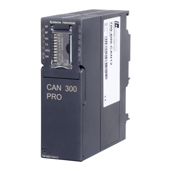
- Page 1 CAN 300 PRO CAN Communication Module for S7-300 ® Start-Up Guide for CANopen Edition 3 / 22.12.2011 Systeme Helmholz GmbH | Hannberger Weg 2 | D-91091 Großenseebach Phone +49 9135 7380-0 | Fax +49 9135 7380-110 | info@helmholz.de | www.helmholz.com...
- Page 3 (photocopy, microfilm, or other method) without the express written permission of Systeme Helmholz GmbH, not even for use as training material, or using electronic systems. All rights reserved in the case of a patent grant or registration of a utility model or design.
- Page 4 Revision history of this document: Edition Date Revision 29.9.2009 1st version 30.04.2010 Corrections for CANParam V4.20 and Firmware V1.20 Correction of the “SF” LED behavior and further small 22.12.2011 corrections...
-
Page 5: Table Of Contents
Connecting to the PC Configuring the CAN Module Creating a new project Setting the master Setting the slave Importing a project into the CAN 300 PRO First diagnosis Scan for slaves Preparations in the PLC Loading data handling blocks PLC in the RUN state... - Page 6 What Else Is Required … I/O area in the PLC Monitoring slave devices Writing SDOs in the slave device ® Operating conditions for CANopen slave devices Troubleshooting Looking for errors Training Start-up support Start-up Guide CAN 300 PRO...
-
Page 7: Introduction
Each section deals with a separate step and the steps are to be performed one after the other. The left-hand margin of the document shows important notes and references to sections of the CAN 300 PRO manual, which you should have close by. What you require ... -
Page 8: Setting Up The Hardware
The CAN 300 PRO is connected to the S7-CPU on the S7-300 mounting rail with the backplane bus connector supplied. The DIP switch of the CAN 300 PRO has no function in this start- Manual: Section 2 up application because all settings are made in the project. -
Page 9: Configuration In The Plc
The module can be used wherever a CP module is allowed, i.e. also in the expansion unit after an interface module. You should change the name of the module to “CAN 300 PRO” for easier identification in the Hardware Configurator. -
Page 10: Connecting To The Pc
The “Basic parameters” tab card has not function with the CAN 300 PRO. Connecting to the PC Connect a USB cable to the CAN 300 PRO and connect it to your If you are connecting the CAN 300 PRO to your PC for the first Manual: Section 6.2 time, the USB driver will be installed. -
Page 11: Configuring The Can Module
Activate the “wizard” with “Set project” in the “Project” menu. You will now be guided through some dialog boxes in which basic settings about your project are queried. Manual: Section 6.4 Make the settings as shown in the following dialog boxes. Start-up Guide CAN 300 PRO... - Page 12 In this dialog box, select the CAN baud rate, which is preset for ® your CANopen device. We recommend setting lower baud rates, such as 500 kpbs for initial start-ups. Start-up Guide CAN 300 PRO...
-
Page 13: Setting The Master
The options in the Start-up behavior group box can be retained Set the PLC I/O buffer as described above; matching parameters will be set for the Step 7 data handling modules later Leave the remaining parameters as they are already set. Start-up Guide CAN 300 PRO... -
Page 14: Setting The Slave
If the node ID of the “Scan for slaves” function after importing the project created so device is not known, the ® far into the CAN 300 PRO (see below) in the “Online / CANopen “Scan to slaves” Tools” menu. function will help! Importing a project into the CAN 300 PRO Activate the “Upload”... -
Page 15: First Diagnosis
” tab card. Press the “Connect” button below right. The status of the CAN controller in the CAN 300 PRO is displayed in the controller status on the right-hand side of the dialog box. This should show 0x00 in the error register and the error Manual: Section 6.7.2... -
Page 16: Scan For Slaves
CAN bus, the baud rate is wrong, or the cabling is not correct. If the CAN device does For the CAN 300 PRO to be able to detect a CAN device as a not support the SDO ®... -
Page 17: Preparations In The Plc
® You will find the project as “C3PRO_CANopen _V1x.ZIP” and newer in the “STEP7\CAN 300 PRO” directory. Open this project to use the blocks. Copy the blocks into the project you created with your hardware configuration and transfer all block to the PLC. -
Page 18: Plc In The Run State
PLC in the RUN state Start the PLC to put the CAN 300 PRO into the “operational” mode, too. On every STOP RUN transition of the PLC, the CAN 300 PRO ® tries to start the CANopen bus and start the devices defined in the project. -
Page 19: Leds Of The Can 300 Pro
LEDs of the CAN 300 PRO The LEDs of the CAN 300 PRO can also be a great help. The “SF” LEDs should not be lighted; otherwise there is a system error. If the “BF” LED is lighted, a CAN error is still present. Check the cabling and the CAN baud rate of all bus nodes. -
Page 20: Assignment Of The Process Data
Assignment of the Process Data If the CAN 300 PRO has been able to detect the device on the CAN bus, the next step is to assign the process data of the device (PDOs) to the PLC. There are up to 8 transmit PDOs (TPDO) and 8 receive PDOs (RPDO). -
Page 21: Setting The Pdo Mapping
For further information on this, see Section 6.4.5 in the CAN 300 PRO Manual. Now proceed exactly as described above for all PDOs you know about and require. Make sure that there are no overlaps in the memory area of the PLC. Start-up Guide CAN 300 PRO... -
Page 22: Defining The Pdo Mapping In The Slave
For this purpose, activate the “Transmit PDO mapping to the slave” option and enter the require SDOs in the list. Make sure the data types are correct. You can find out about them in the Manual: Sections 6.4.3 device manual. and 6.4.4 Start-up Guide CAN 300 PRO... -
Page 23: Testing The Pdo Mapping
® The SDO abort code is the response of the CANopen slave device to the writing or reading of an SDO. The CAN 300 PRO writes and reads some SDOs as the master starts in order to make the ®... -
Page 24: Emergency Messages
Byte 6 Byte 7 Byte 8 Emergency Error Code Error Register Manufacturer-specific Error (0x1001) The manual of your device should contain a list of the possible emergency messages, or ask the manufacturer of your device. Start-up Guide CAN 300 PRO... -
Page 25: Programming In The Plc
® The block FB 21 “CANopen IO Write” is called at the end of the PLC cycle to write the new output data (RPDOs of the slave) from the PLC into the CAN 300 PRO. CALL 21 , DB21 Base :=256 Source:=P#A 50.0 BYTE 60... -
Page 26: How Pdos Are Assigned To The Plc
PDO data. However, be sure to adapt the parameters in FB 20 and FB 21 accordingly. CALL 20 , DB20 Base :=256 Dest :=P#DB10.DBX 0.0 BYTE 400 STAT :=MW20 :=M22.6 RetVal :=MW24 NewData:=M22.0 Start-up Guide CAN 300 PRO... - Page 27 CANParam and test this in the debug tools. The following sections will explain what else you require... I/O area in the PLC In the I/O area of the CAN 300 PRO, which is located as from address PIB 256 in our example, you obtain information about ®...
- Page 28 CAN bus active either in PIB 263 or, if there are multiple devices on the bus, in detail by using the FB 22 ® Manual: Section 7.7.3 “CANopen Service” with the Livelist. Start-up Guide CAN 300 PRO...
- Page 29 The required SDOs can be inserted as a list into the CANParam on the slave. Manual: Section 6.4.6 SDOs can also be written or read from the PLC during operation. ® For this purpose, use the FB 24 “CANopen SDO.” Manual: Section 7.7.5 Start-up Guide CAN 300 PRO...
- Page 30 ® with the CAN 300 PRO via CANopen Alternatively, such a device can be used in Layer 2 mode of the CAN 300 PRO. Please contact us about this … Start-up Guide CAN 300 PRO...
- Page 31 CANopen Abortcode If these tips do not help, contact our support Either by phone on +49 9135 7380-0 or by e-mail to support@helmholz.de. If information about their slave device is also at hand (manual), please also send this information.
- Page 32 ® the entire topic of CAN, the CANopen protocol, start-up and programming of the CAN 300 PRO and an error analysis. You will find the next dates in the Internet at www.helmholz.com. Training courses can also be held on your site.
- Page 33 Notes Start-up Guide CAN 300 PRO...
Need help?
Do you have a question about the CAN 300 PRO and is the answer not in the manual?
Questions and answers