
Subscribe to Our Youtube Channel
Related Manuals for Ecler NXA Series


Summary of Contents for Ecler NXA Series
- Page 1 NXA Series DIGITAL MATRIXES AND PROCESSORS Powered Digital Audio Managers USER MANUAL 50-0257-0109 NXA SERIES...
-
Page 2: Table Of Contents
11 TP-NET PROTOCOL INTRODUCTION ................20 12 NXA DIGITAL AUDIO MANAGER SERIES ................ 23 13 ERROR CODES FOR ECLERNET DEVICES............... 27 13.1 COMMON ERROR CODES (to all EclerNet - TP-NET compatible devices) ..27 13.2 NXA SERIES SPECIFIC ERROR CODES ................. 27... -
Page 3: Hardware
IMPORTANT REMARK The lightning flash with arrowhead symbol, within an equilateral triangle, is intended to alert the user to the presence of uninsulated “dangerous voltage” within the product’s enclosure that may be of sufficient magnitude to constitute a risk of electric shock to persons. The exclamation point within an equilateral triangle is intended to alert the user to the presence of important operating and maintenance (servicing) instructions in the literature accompanying the appliance. -
Page 4: Important Safety Instructions
IMPORTANT SAFETY INSTRUCTIONS Read these instructions. 2. Keep these instructions. 3. Heed all warnings. 4. Follow all instructions. 5. Do not use this apparatus near water. 6. Clean only with dry cloth. 7. Do not block any ventilation openings. Install in accordance with the manufacturer’s instructions. -
Page 5: Important Note
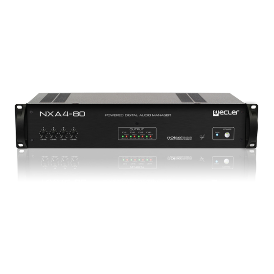
Technical Services. Ecler NXA Series comes with a 3-year warranty. INTRODUCTION The NXA series consists of four models with 4 channels and two models with 6 channels: • NXA4-80: 4 x 80 W RMS @ 4 •... -
Page 6: Main Features Of Nxa Series
Main features of NXA Series • 4/6 analogue audio inputs • 4/6 amplified output channels (SINGLE (independent), PARALLEL or BRIDGED modes) • 4/6 GPI remote control ports (compatible with 0-10VDC analogue devices, such as WpaVOL and WpaVOL-SR wall panels). A GPI port can control one or more inputs or outputs (volume) or manage the recall of presets 1 to 5 (GPI-1 only) •... -
Page 7: Installation
All NXA series products are supplied with plastic washers in order to be mounted in a rack without damaging the mounting ears. -
Page 8: Mains Connection
Mains connection NXA series products are powered by 110-120, 220-240VAC, 47 / 63Hz, depending on the country (see nameplate on the device). The mains cables must not be near the shielded cables carrying the audio signal, as this could cause humming. -
Page 9: Output Connections
TP-NET external control protocol. A 3-pin Euroblock connector for the integrated RS-232 (11) interface also allows the device remote control using the TP-NET protocol. Please refer to the EclerNet Manager software manual at www.ecler.com. and TP-NET protocol for more information. -
Page 10: Gpi Remote Control Ports
GPI remote control ports The NXA series rear panel provides 4 or 6 (depending on the model) 0-10VDC remote control ports (13), labeled "GPI 1-6", to which you can connect analogue devices such as the Wpa series wall panels. With the EclerNet Manager application, a function can be assigned to each of these ports: a GPI port can control one or more inputs or outputs (volume) or manage the presets #1-5 recall (GPI-1 only). -
Page 11: Fault Port (Equipment Self-Diagnosis)
To turn them off the sequence should follow an inverse pattern. Front panel LED indicators NXA series products have the following LEDs on their front panel: • SP indicators (2): indicate a signal presence in the amplification channels. These indicators light up when the input signal exceeds a -40dB threshold. - Page 12 LEDs blink when the "Device Finder" function is activated in EclerNet Manager application. That’s useful for identifying a physical device from its virtual counterpart in this application. Please refer to the EclerNet Manager software manual at www.ecler.com for more information.
-
Page 13: Front Panel Controls
EclerNet Manager application. Please refer to the EclerNet Manager software manual at www.ecler.com more information. Moreover, the EclerNet Manager application allows the DSP processing management (volume, phase, EQ, compression, delay, customised input mixes for each output channel, priority or DUCKER function, etc..) for each channel, each channel being used... -
Page 14: Cleaning
CLEANING The front panel should not be cleaned with dissolvent or abrasive substances because silk-printing could be damaged. To clean it, use a soft cloth slightly wet with water and neutral liquid soap; dry it with a clean cloth. Be careful that water never gets into the amplifier through the holes of the front panel. -
Page 15: Block Diagram
BLOCK DIAGRAM... -
Page 16: Technical Characteristics
10 TECHNICAL CHARACTERISTICS NXA4-80 NXA6-80 NXA4-200 NXA6-200 NXA4-400 NXA4-700 POWER 20Hz-20kHz 1% THD 1 Channel @ 2 (RMS) 1220 W 1 Channel @ 4 (RMS) 85 W 84 W 202 W 218 W 426 W 730 W 1 Channel @ 8 (RMS) 51 W 49 W 121 W... - Page 17 DIGITAL Processing: A/D & D/A 24 bit, 48kHz. 115dB AKM Codec DSP 32/64 bits Latency 2ms Analog Input headroom: +18 dBV = +21dBu Digital Input attenuator: Stepless from – to +0dB Input Impedance: Balanced, 22k Maximum Delay: 1s (343.4m) for each channel Delay resolution: 20.8µs (6mm) Compressor / Limiter: Threshold from -36dBV to +18dBV...
-
Page 18: Software
SOFTWARE EclerNet Software - Realtime full GUI of all functions and controls thru Ethernet with interactive graphical display - Grouping mode channels or devices - Automated report generation - Remote power on with programmable delay. - Up to 256 devices on same net. - Autodiscovery devices feature - Routing capability through NAT gateways. - Page 19 TP-NET PROTOCOL SOFTWARE Third-Party NET USER MANUAL...
-
Page 20: Tp-Net Protocol Introduction
• Stop bits: 1 • Flow control: None In case the Ecler device has an Euroblock connector for the RS-232 interface, the serial cable wiring, from the device’s connector to a standard DB9 serial interface connector, must be the following: The protocol is simple and direct, making it easy to read, write and modify the generated code. - Page 21 The available messages are built with one or more fields separated with blank spaces ( = blank space): <TYPE> [PARAM1] [PARAM2] [PARAM3] [PARAM4][LF] The first field (TYPE) defines the message type and then, the required parameters for it (each kind of message requires a given number of parameters). The field TYPE can have these values:...
- Page 22 <Input Channel> & <Output Channel> are numerical values that identify an input or output channel of the EclerNet device. For the NXA series it can be within the [1..4] or [1..6] range, for 4 or 6 channel amplifiers. • <Preset Number>...
-
Page 23: Nxa Digital Audio Manager Series
12 NXA DIGITAL AUDIO MANAGER SERIES IMPORTANT NOTE: The communication must be started with the client sending the first message SYSTEM CONNECT to the EclerNet device. Otherwise, the commands from the client to the EclerNet device will be ignored. See TP-NET PROTOCOL INTRODUCTION chapter for additional information. - Page 24 INFO_NAME Gets the Device Name INFO_MODEL Gets the Device Model INFO_VERSION Gets the Firmware Version INFO_MAC Gets the Device MAC address VIRTUAL_CONTROL <Virtual Gets the Virtual Control value Control>...
- Page 25 TYPE PARAM1 PARAM2 PARAM3 PARAM4 DESCRIPTION POWER ON/OFF Sets the Device Power status PRESET <Preset Number> Sets the current PRESET OLEVEL <Output <Level> Sets the current LEVEL of an Output Channel Channel> XLEVEL <Input Channel> <Output <Level> Sets the current LEVEL of a Matrix point Channel>...
- Page 26 XLEVEL <Input Channel> <Output <Level> Shows the current LEVEL of a Matrix point Channel> OMUTE <Output YES/NO Shows the current MUTE status of an Output Channel Channel> XMUTE <Input Channel> <Output YES/NO Shows the current MUTE status of a Matrix point Channel>...
-
Page 27: Error Codes For Eclernet Devices
13 ERROR CODES FOR ECLERNET DEVICES 13.1 COMMON ERROR CODES (to all EclerNet - TP-NET compatible devices) ERROR ID DESCRIPTION TPNET_ERROR_NONE = 0, TPNET_ERROR_INVALID_FIELD_TYPE, TPNET_ERROR_INVALID_FIELD_PARAM1, TPNET_ERROR_INVALID_FIELD_PARAM2, TPNET_ERROR_INVALID_FIELD_PARAM3, TPNET_ERROR_INVALID_FIELD_PARAM4, 13.2 NXA SERIES SPECIFIC ERROR CODES ERROR ID DESCRIPTION UDP_ERROR_TIMEOUT_PONG, UDP_ERROR_CONNECT_WHILE_CONNECTED, UDP_ERROR_DISCONNECT_WHILE_UNCONNECTED, UDP_ERROR_INVALID_CLIENT_IP, UDP_ERROR_MESSAGE_TOO_LONG, UDP_ERROR_UNSUPPORTED_MESSAGE, UDP_ERROR_UNSUPPORTED_PRESET_NUMBER,... - Page 28 NEEC AUDIO BARCELONA S.L. reserves the right to make changes or improvements in the design or manufacturing that may affect these product specifications. For technical queries contact your supplier, distributor or complete the contact form on our website, Support / Technical requests. Motors, 166‐168 08038 Barcelona ‐ Spain ‐ (+34) 932238403 | information@ecler.com www.ecler.com...
Need help?
Do you have a question about the NXA Series and is the answer not in the manual?
Questions and answers