Advertisement
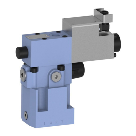
Proportional pressure reducing - relief valve,
zawór redukcyjno - przelewowy propor-
intrinsically safe IWZCPE10
NS 10 | p
30 MPa | Q
max
DATA SHEET - OPERATION MANUAL
APPLICATION
Proportional pilot operated, intrinsically safe pressure reducing - relief valve
IWZCPE10... type is used for maintaining the constant pressure indepen-
dently of the flow direction.
Pressure adjusting is the function of the current supplied to the coil of
the proportional solenoid. The valve is intended to work in an explosive
atmosphere in underground minings (group I) and in machines working
near flammable substances in the form of gases, vapours, mists (group II).
The valve has certificates of intrinsic safety:
ia IIA T3 Gb. It can work with an output intrinsically safe circuit „ia" or „ib"
of max. parameters: Ui = 15 V, Ii = 2 A, Ci = 0, Li = 0.
DESCRIPTION OF OPERATION
Intrinsically safe proportional pressure reducing-relief valve IWZCPE10...
type among others consists of the intrinsically safe pilot valve 1, IWZEP6...
type, proportional solenoid 2, adjusting nozzle 3, and poppet 4.
The reduced pressure from port A through the nozzles system acts on the
bottom and top side of the spool 6, and on poppet 4 connected with the
proportional solenoid core 2. The strength of poppet 4 clamp to the adjust-
ment nozzle 3 is proportional to the solenoid current 2.
If pressure in port A (of the control flow) will be higher than the pressure
set on the pilot valve, it will open and the fluid will be drained to the tank
through port Y. The opening of the pilot valve interferes the balance state
on the main spool, and causes self-emerging of new clearance throttling the
pilot flow, so that the pressure behind is independent of the amount of fluid.
The valve works as a pressure relief valve when in port A the pressure is
raised to the value that will close the way from P to A and connect A and
T ports. It secures the system from excessive pressure increase in A port,
stabilising the pressure at the requested level, independently from the
flow direction. Between the valve housing 1 and the main housing 5, the
pressure limiting valve 7 is placed. The value of set pressure is regulated
with adjusting element 8.
NOTE:
The control nozzle 3 is factory set and its setting shall not be changed (it can
cause damage of the valve or system, where the valve works). Regulated
pressure (in port P) is the function of the current applied on the proportional
solenoid coil 2, only till pressure value set at the pressure reducing valve 7.
In order to set the pressure at the pressure reducing valve 7 the maximum
current shall be applied on the solenoid 2 and by means of the adjustment
element 8, the maximum or other requested working pressure shall be set.
IWZCPE10 | Data Sheet - Operation manual
60 dm
/min | WK 432 670
3
max
IM1 Ex ia I Ma;
1
3
II 2G Ex
B
1
7
5
7
6
T
A
5
6
T
HYDRAULIC DIAGRAM
1/6
1/6
1/6
2
4
Y
T
2
4
3
8
Y
T
B
8
P
Y
A
P
Y
A
A
P
T
Y
P
T
Y
WK 432 670 | 12.2020
15
15
Advertisement
Table of Contents

Related Manuals for Ponar Wadowice IWZCPE10


Summary of Contents for Ponar Wadowice IWZCPE10
- Page 1 DATA SHEET - OPERATION MANUAL APPLICATION Proportional pilot operated, intrinsically safe pressure reducing - relief valve IWZCPE10… type is used for maintaining the constant pressure indepen- dently of the flow direction. Pressure adjusting is the function of the current supplied to the coil of the proportional solenoid.
-
Page 2: Technical Parameters
ELECTRIC DIAGRAM max. flow 60 dm /min control method PWM 150Hz signal version IWZCPE10 ...N... without LED light signalling hysteresis < 7% max. pressure max. current of the solenoid coil I 0,3 A resistance of solenoid coil winding at the temp. of 20°C 20,2 Ω... - Page 3 Ø 8 in depressurized condition 11,2 (max) - 4 holes 0,01/100 91 (min.) – connection element ISO 4401-05 not used by valve (P, T, A, B) 0,63 IWZCPE10 type 0,01/100 0,63 IWZCPE10 | Data Sheet - Operation manual WK 432 670 | 12.2020...
-
Page 4: Performance Curves
P→A (funkcja redukcyjna) 0,05 0,25 0,15 Q [dm /min] I [mA] flow direction P → A (reduction function) kierunek przepływu P→A (funkcja redukcyjna) Q [dm /min] Q [dm /min] IWZCPE10 | Data Sheet - Operation manual WK 432 670 | 12.2020... -
Page 5: How To Order
PN – EN ISO 4762 (PN/M – 82302) 4 pcs/set. Tightening torque for screws M = 15 Nm. Subplate and mounting screws must be ordered separately. IWZCPE10 | Data Sheet - Operation manual WK 432 670 | 12.2020... - Page 6 CONTACT PONAR Wadowice S.A. tel. +48 33 488 21 00 ul. Wojska Polskiego 29 www.ponar-wadowice.pl 34-100 Wadowice IWZCPE10 | Data Sheet - Operation manual WK 432 670 | 12.2020...
Need help?
Do you have a question about the IWZCPE10 and is the answer not in the manual?
Questions and answers