Advertisement
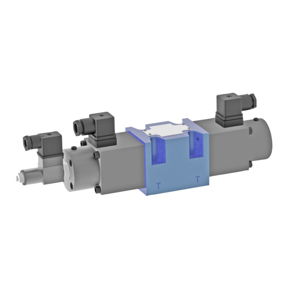
Proportional valve USEB 10
NS 10 | p
35 MPa | Q
max
max
DATA SHEET - OPERATION MANUAL
APPLICATION
Proportional directional valve type USEB10... is used to control
the direction and speed of movement of an actuator. Flow rate
of hydraulic oil directed to the actuator is adjusted by change of
electric current supplying the solenoid coil.
a
a
5
5
DESCRIPTION OF OPERATION
The proportional directional valve type USEB 10 sonsists of the housing
1, solenoids 2 and 4,inductive offset detector 3, spool 5, springs 6 and 7.
Electric regulator (30 RE ...) can be included with thevalve. The regulator is
applied to control proportionalsolenoids and receive the signals from offset
detector.The proportional solenoid 2 or 4 pushes the spool fromits neutral
position. The neutral position is held by thesprings 6 and 7. The inductive
offset detector hasdouble stroke. Its range allows to measure the offsetof
the spool from neutral position to the right or left.The offset of the spool
TECHNICAL DATA
hydraulic fluid
required fluid cleanliness class
nominal fluid viscosity
viscosity range
fluid temperature range (in the tank)
ambient temperature range
max. working pressure
hysteresis
repeatability
sensitivity
hydr. zero shif t
working position
assembly and operation requirements at: www.operating-conditions.ponar.pl
USEB10 | Data Sheet - Operation Manual
64 dm
/min | WK 420 560
3
2
7
2
7
mineral oil ISO 4406 class 20/18/15
37 mm
/s w temperature 55 °C
2
2,8 ÷ 380 mm
/s
2
rec: 40 ÷ 55°C; max.: -20 ÷ 70 °C
-20 ÷ 50 °C
35 MPa (ports P, A, B); 21 MPa (port T)
<1%
<1%
≤ 0,5% of nominal signal
0,2%/ °C
any position
USEB10 - 3X/E - 32
USEB10 - 3X/E - 32
T
A
P
B
T
T
A
P
B
T
1
3
6
1
3
6
5 is transmitted electrically asinitial data. It is held in the signal sent by the
electronicregulator in form of current with certain intensity that ischanged
by the solenoid 2 or 4 into force pushing thespool 5 against spring 6 or 7.
Simultaneously the offsetdetector 3 determines actual position of the
spool and inform of electrical signals sends as feedback to theelectronic
regulator. The both signals: initial data andactual value are compared in
the electronic regulator,which sends a new signal correcting the position of
thespool 5 in order to adjust it in conforming with the initialsignal
with 2 solenoids
weight
with 1 solenoids
nom. power of the solenoid
22,5 W
10 Ω (for cold solenoid 20 °C )
coil resistance
14 Ω (for max heated solenoid)
inductive switch stroke
± 4,5 mm linear
linearity tolerance
1%
coil I
coil II
resistance of sensor coil
coil III
for valve with
2 solenoids
electronic controllers
for valve with
1 solenoid
1/6
b
b
4
4
7,65 kg
5,65 kg
56 Ω
56 Ω
112 Ω
32RE21 acc. to WK 495 774
32RE11 acc. to WK 495 772
WK 420 560 | 05.2021
Advertisement
Table of Contents

Related Manuals for Ponar Wadowice USEB 10


Summary of Contents for Ponar Wadowice USEB 10
- Page 1 USEB10 - 3X/E - 32 DESCRIPTION OF OPERATION The proportional directional valve type USEB 10 sonsists of the housing 5 is transmitted electrically asinitial data. It is held in the signal sent by the 1, solenoids 2 and 4,inductive offset detector 3, spool 5, springs 6 and 7.
- Page 2 SCHEMATY HYDRAULIC DIAGRAMS symbole graficzne rozdzielaczy 3-położeniowych graphical symbols of 3-position spool valves symbole graficzne suwaków położenia robocze i położenia robocze versions USEB10 wersje USEB6 ... positions: working and interim working pośrednie E, E1, E2 NOTES: for spools E1 i W1 flows are: P →...
- Page 3 OVERALL AND CONNECTION DIMENSIONS 11 - 4 counterbores 6,6 - 4 holes 11 - 4 counterbores 6,6 - 4 holes 69,5 69,5 10,5 10,5 18,5 70,5 18,5 70,5 solenoid on a side solenoid on b side connector on a side - type ISO 4400 (DIN 43650) connector on b side - type ISO 4400 (DIN 43650) manual override 18, 5...
- Page 4 CHARAKTERYSTYKI ν measured at viscosity of hydraulic fluid = 41 mm /s and temperature t = 50 °C ® ® ® ® version USAB10... 16 ...; f P A / B T or P B / A shift of spool [%] ®...
- Page 5 4 pcs/set delivered on separate order G 534/01 - threaded connection G ¾ tightening torque of the screws M = 15 Nm. CONTACT PONAR Wadowice S.A. tel. +48 33 488 21 00 ul. Wojska Polskiego 29 www.ponar-wadowice.pl 34-100 Wadowice USEB10 | Data Sheet - Operation Manual...
- Page 6 CONTACT PONAR Wadowice S.A. tel. +48 33 488 21 00 ul. Wojska Polskiego 29 www.ponar-wadowice.pl 34-100 Wadowice USEB10 | Data Sheet - Operation Manual WK 420 560 | 05.2021...
Need help?
Do you have a question about the USEB 10 and is the answer not in the manual?
Questions and answers