Advertisement
Quick Links
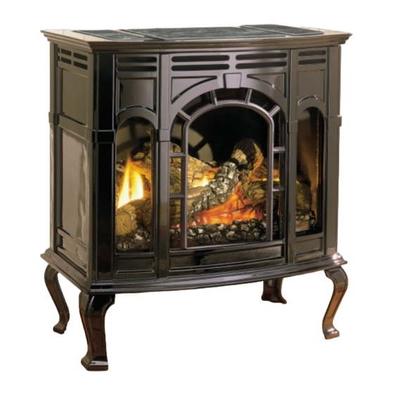
This appliance may be installed in an aftermarket
permanently located, manufactured (mobile)
home, where not prohibited by local codes.
This appliance is only for use with the type of gas
indicated on the rating plate. This appliance is
not convertible for use with other gases, unless a
certified kit is used.
WARNING: If the information in this manual is
not followed exactly, a fire or explosion may
result causing property damage, personal in-
jury or loss of life.
FOR YOUR SAFETY: What to do if you smell
gas:
•
Do not touch any electrical switches
•
Do not try to light any appliance.
•
Do not use the phone in your building.
•
Immediately call your gas supplier from a
neighbor's phone.
•
Follow the gas supplier's instructions.
•
If you cannot reach your gas supplier, call
the fire department.
WARNING: Improper installation, adjustment,
alteration, service or maintenance can cause
injury or property damage. Refer to this manual.
For assistance or additional information consult
a qualified installer, service agency, or the gas
supplier.
R-5086
INSTALLATION INSTRUCTIONS
OWNER'S MANUAL
AVERTISSEMENT: Une installation, un réglage,
une modification, un entretien ou une maintenance
incorrects peuvent entraîner des dommages
matériels, des lésions corporelles ou la perte de vies
humaines. Consulter le manuel des usagers fourn
avec ce générateur d'air chaud.
AND
CAST IRON
DIRECT VENT FIREPLACE
MODEL
CIDV-30-7
EFFECTIVE DATE
AUGUST, 2000
Cet appareil peut être installé dans une maison
préfabriquée (mobile) déjà installée à demeure si
les règlements locaux le permettent.
Cet appareil doit être utilisé uniquement avec les
types de gaz indiqués sur la plaque signalétique. Ne
pas l'utiliser avec d'autres gaz sauf si un kit de
conversion certifié est installé.
AVERTISSEMENT: Quiconque ne respecte pas à
la lettre les instructions dans le présent manuel
risque de déclencher un incendie ou une explosion
entraíant des dommages matériels, des lésions
corporelles ou la perte de vies humaines.
POUR VOTRE SÉCURITÉ: Que faire si vous
sentez une odeur de gaz:
•
Ne pas tenter d'allumer d'appareil.
•
Ne touchez à aucun interrupteur. Ne pas vous
servir des téléphones se trouvant dans le
bâtiment où vous vous trouvez.
•
Évacuez la pièce, le bâtiment ou la zone.
•
Appelez immédiatement votre fournisseur de
gaz depuis un voisin. Suivez les instructions du
fournisseur.
•
Si vous ne pouvez rejoindre le fournisseur de
gaz, appelez le service dos incendies.
Page 1
Advertisement

Related Manuals for Empire Comfort Systems CIDV-30


Summary of Contents for Empire Comfort Systems CIDV-30
- Page 1 INSTALLATION INSTRUCTIONS OWNER'S MANUAL CAST IRON DIRECT VENT FIREPLACE MODEL CIDV-30-7 EFFECTIVE DATE AUGUST, 2000 This appliance may be installed in an aftermarket Cet appareil peut être installé dans une maison préfabriquée (mobile) déjà installée à demeure si permanently located, manufactured (mobile) les règlements locaux le permettent.
- Page 2 Instructions to Installer Specifications Model CIDV-30 Installer must leave instruction manual with owner after Input BTU/HR (KW/H) Max (LP/NAT) 30,000 (8.7) installation. BTU/HR (KW/H) Min. LP 22,000 (6.4) Installer must have owner fill out and mail warranty card BTU/HR (KW/H) Min. Nat.
-
Page 3: Safety Information For Users Of Lp-Gas
SAFETY INFORMATION FOR USERS OF LP-GAS Propane (LP-Gas) is a flammable gas which can cause fires by point with the members of your household. Someday when there may not be a minute to lose, everyone's safety will and explosions. In its natural state, propane is odorless and colorless. - Page 4 Installation in Residential Garages TURER, PROVINCIAL OR TERRITORIAL AUTHORITIES HAV- Gas utilization equipment in residential garages shall be installed so that ING JURISDICTION AND IN ACCORDANCE WITH THE REQUIRE- all burners and burner ignition devices are located not less than 18" MENTS OF THE CAN/CGA-B141.1 OR CAN/CGA-B141.2 INSTAL- (457mm) above the floor.
- Page 5 Figure 1 Method of Installing a Tee Fitting Sediment Trap Pressure Testing of the Gas Supply System 1. To check the inlet pressure to the gas valve, a 1/8" (3mm) N.P.T. plugged tapping, accessible for test gauge connection, must be placed immediately upstream of the gas supply connection to the appliance.
- Page 6 Appliance Hardware Package (Figure 6) Figure 4 90° ELBOW 90° ELBOW 24" PIPE SECTION 24" PIPE SECTION Figure 6 (610mm) Appliance Hardware Package Parts List Part Part Quantity Description Number Supplied 55 1/2" 55 1/2" 1/4-20 x 1" Phillips Head Bolt R-3188 (141cm) 1/4-20 x 3/8"...
- Page 7 Figure 7 to protect the porcelain finish. The exterior of the porcelain 7. Refer to Figure 8, attach casing support to rear cover with (4) 10 x 1/2" casting pieces should be facing the non-abrasive surface. screws. The rear cover has (4) keyholes for attachment to the casing 2.
- Page 8 Figure 9 8. Position the completed portion of the casing in the approximate location for installation as the completed assembly will be heavy. 9. Refer to Figure 9, removing protective packing foam from casing front and window. Remove the (1) 3/4" bolt and (1) 1/4" washer from top of window.
- Page 9 15. Attach casing front to outer casing as described in Step 11. Stone Inlay Replacement of Standard Grille Top 16. Place the casing top onto the outer casing. The casing top nests into Whenever the standard grille top is replaced with a stone inlay you must the outer casing.
- Page 10 Delayed Ignition Reset Switch Assembly (Figure 14) Under no circumstances should combustible materials (including siding) Attach black wire from REMOTE/OFF/ON switch to the front 1/4" male be closer than 2" from the top of the 6 5/8" pipe or closer than 1" on the tab on the reset switch.
- Page 11 Venting Graph (Dimensions in Feet) (Figure 16) To Use the Vent Graph 1. Determine the height of the center of the termination. Using this EXAMPLE A: dimension on the Venting Graph, locate the point it intersects with the If the vertical rise from the appliance outlet is 21 feet, the horizontal run slanted graph line, or the right edge of the graph.
- Page 12 Installation of Restrictor Plate (Figure 18) Service Notes The restrictor plate is to be used only in a completely vertical vent installation. The restrictor plate can be used when the vertical vent rise is between 10 feet and 25 feet. In a vertical vent rise the rear (yellow) flame on the main burner can be reduced due to the drawing action from the flue exhaust pipe and the air inlet pipe.
- Page 13 Termination Clearances (Figure 19) Termination clearance for buildings with combustible and noncombustible exteriors. Figure 19 Vertical Sidewall Installations Important! Minimum clearance between vent pipes and combustible materials is one inch (1") (25mm) on, bottom and sides and (2") (51mm) on top. Important! When vent termination exits through foundation less than 20"...
- Page 14 Vent Clearances (Figure 20) Figure 20 clearance to non-mechanical air supply inlet to building or the combustion air inlet to any other appliance [*12 inches (30cm) *Clearance above grade, veranda, porch, deck or balcony [*12 minimum for appliances ≤ 100,000 Btuh (30 kW) inches (30cm) minimum] 36 inches (90cm) minimum for appliances >...
- Page 15 Installing Vent Components (Figure 21 and Figure 22) Begin the vent system installation by installing the first component, a straight pipe on the top of the appliance,or rotate the vent elbow to the horizontal positon then add horizontal and vertical pipe lengths and then a horizontal or vertical termination kit.
- Page 16 Position a plumb bob directly over the center of the vertical vent component and mark the ceiling to establish the center point of the vent. Drill a hole or drive a nail through this center point and check the floor above for any obstructions such as wiring or plumbing runs.
- Page 17 Figure 27 Horizontal Terminations (Figure 28) Attach and secure the termination to the last section of horizontal venting by rotating and interlocking the ends as previously described. Figure 28 NOTE: Termination cap should pass through the wall firestop from the exterior of the building. Adjust the termination cap to its Vertical Terminations (Figures 29, 30 and 31) final exterior position on the building.
- Page 18 Figure 30 CAUTION: Treatment of firestop spacers and construction of the chase may vary with the type of building. These instructions are not Figure 29 substitutes for the requirements of local building codes. Therefore, Note that for steep roof pitches, the vent height must be increased. In your local building codes must be checked to determine the high wind conditions, nearby trees, adjoining roof lines, steep pitched requirements for these steps.
- Page 19 General Glass Information 8. Grasp bottom of glass frame, push upward and insert glass frame Only glass approved for use in Empire Comfort Systems, Inc. fireplaces into glass frame support top, push inward and insert glass frame may be used for replacement. The glass replacement should be done by into glass frame guide.
- Page 20 Replacement of Gasket on Glass Panes (Figure33) Pilot Flame Pattern (Figure 34 and Figure 35) 1. Remove casing top from outer casing. Figure 34 shows a correct pilot flame pattern. The correct flame will be 2. Remove casing front from outer casing. blue and will extend beyond the thermocouple and thermopile.
- Page 21 BEFORE HANDLING. OPERATING INSTRUCTIONS CIDV-30 ON/OFF/REMOTE Switch CIDV-30 is equipped with an ON/OFF/REMOTE switch which is located on the wiring chase. A wire harness is attached to the ON/OFF/ REMOTE switch. The red, black and green (wires) female push-ons attach to the ON/OFF/REMOTE switch. At the opposite end of the wire harness, the black and green (wires) female push-ons attach to the gas valve.
- Page 22 Wiring of ON/OFF/REMOTE Switch with 750 Millivolt Wall Wiring Diagram (Figure 39) Thermostat Accessory and Another Accessory Connect the green and red, stripped and bare, wires on the ON/OFF/ REMOTE switch wire harness to the 750 millivolt wall thermostat AND to the remote receiver that is a component in the FRBC-1, FREC-1 OR to the FWS-1, wall switch.
- Page 23 Initial Lighting (Figure 40) Maintenance & Service Instructions Upon completing the gas line or turning the gas valve "ON" after it has IMPORTANT: Turn off gas before servicing appliance. It is been in the "OFF" position, a small amount of air will be in the lines. recommended that a competent service technician perform these check- When first lighting the appliance, it will take a few minutes for the lines ups at the beginning of each heating season.
-
Page 24: For Your Safety Read Before Lighting
FOR YOUR SAFETY READ BEFORE LIGHTING WARNING: If you do not follow these instructions exactly, a fire or explosion may result causing property damage, personal injury or loss of life. A. This appliance has a pilot which must be lighted by •... -
Page 25: Standing Pilot-Trouble Shooting
STANDING PILOT-TROUBLE SHOOTING With proper installation and maintenance, your new Direct Vent Fireplace should provide years of trouble-free service. If you do experience a problem, refer to the Trouble Shooting Guide below. This guide will assist a qualified service person in the diagnosis of problems and the corrective action to be taken. - Page 26 PLEASE NOTE: When ordering parts, it is very important that part number and description of part coincide. Index Part Index Part Number Description Number Description CI-361 INNER BOTTOM ASSEMBLY R-3436 REMOTE/OFF/ON SWITCH M-164 GASKET - MANIFOLD CI-329 WIRE CHANNEL M-157 GASKET - SEAL BRACKET CI-331 CHANNEL DIVIDER...
- Page 27 R-5086 Page 27...
- Page 28 PLEASE NOTE: When ordering parts, it is very important that part number and description of part coincide. Index Part Index Part Number Description Number Description *CI-006 WINDOW RETAINING TAB R-3715 TOP (NAVY ENAMEL) R-3948 WINDOW (BLACK PAINT) * CI-007 RETAINING TAB - 4 REQUIRED R-3688 WINDOW (BLACK ENAMEL) R-3946...
- Page 29 OPTIONAL BLOWER CIB-2 Direct Vent Fireplace CIDV-30 nstalling Optional CIB-2 Blower Fan Control 1. Loosen, but do not remove, (4) hex-head screws located on the The fan control is a non-adjustable automatic type The fan control will exterior, bottom of the appliance.
- Page 30 Cord Set R-3767-A Wire Harness CI-004 Fan Control Bracket (Use with CIBV-30, CIVF-25, CIVF-25C Only) CI-325 Fan Control Bracket (Use with CIDV-30 Only) R-2503 Fan Control R-2805 Auto/Off/On Switch CI-220 Fan Control Shield (Use with CIVF-25 only) R-1410 Bushing 7/8" D...
Need help?
Do you have a question about the CIDV-30 and is the answer not in the manual?
Questions and answers
does the CIDV-30-1 need a fireproof mat underneath if it's on a wood floor?