Advertisement
Quick Links
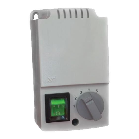
Fan speed controller HC
User guide
Welcome
Thank you very much for purchasing Reventon Group
device. We would like to congratulate you on excellent
choice. Controllers are designed to regulate the rotational
speed of single phase fan motor. They can also be used
to regulate temperature of heating elements. They
are available in several versions, varying maximum current
which device can conduct. The selection of the appropriate
model depends on the number of the devices that have
to be connected to the regulator. Please read and keep this
manual. In case of any doubts please contact directly
the producer Reventon Group sp. z o.o.
Package content
- fan speed controller HC
- user guide
- mounting screws
Service
We offer the warranty of 24 months from the sales day.
Safety rules
The installation of the controller can be made by qualified
electrician. During the installation and all maintenance
work device has to be disconnected from power grid.
Maximum current drawn by controller HC cannot exceed
the maximum rated current for particular regulation stage
(see table below).
Transport and storage
The original packaging used by the manufacturer
is a warranty of safe transport and storage. The device
should be kept in original packaging in temperature from
5°C to + 50°C.
Technical data
- Power supply 230 V
- Other electrical parameters:
Regulation stage U
MODEL
1
2
3
HC 3.0 A
115/2.2
135/2.5
155/2.8
HC 5.0 A
80/4.0
105/4.3
135/4.6
HC 7.0 A
80/6.0
105/6.3
135/6.6
HC 14.0 A
80/8.0
105/9.5
135/11.0
- Degree of protection: IP 54
- Ambient temperature: ≥ 40°C
- Protection: resistant to occasional overload; automatic
thermal switch (HC 3.0 A - HC 7.0 A); not-automatic thermal
switch type WEBER (HC 14.0 A)
- Compliance with the norm: PN-EN61558-2-13
- Insulation class: II
Dimensions
[V] / I
[A]
MODEL
r
r
4
5
HC 3.0 A
180/3.0
230/3.0
HC 5.0 A
HC 7.0 A
170/5.0
230/5.0
HC 14.0 A
170/7.0
230/7.0
Electrical diagram
170/12.5
230/14.0
DIMENSIONS [mm]
WEIGHT
A x B x C
D x E
φ
kg
86 x 166 x 91
71 x 155
M4
2.5
123 x 240 x 125
105 x 220
M6
4.5
123 x 240 x 125
105 x 220
M6
5.5
146 x 272 x 140
113 x 255
M6
10.5
Advertisement

Related Manuals for REVENTON HC 3.0 A


Summary of Contents for REVENTON HC 3.0 A
- Page 1 They are available in several versions, varying maximum current thermal switch (HC 3.0 A - HC 7.0 A); not-automatic thermal which device can conduct. The selection of the appropriate switch type WEBER (HC 14.0 A)
- Page 2 Installation Precautions: • ensure the ambient temperature is ≥ 40°C • during the operation the housing can get hot • there should be free space 200 mm around the device • when you install more than one controller the distance between them must be at least 200 mm •...
Need help?
Do you have a question about the HC 3.0 A and is the answer not in the manual?
Questions and answers