Table of Contents
Advertisement
Quick Links
Advertisement
Table of Contents

Related Manuals for Fracarro GALAXIA


Summary of Contents for Fracarro GALAXIA
- Page 1 GALAXIA HIGH DENSITY DIGITAL HEADEND User Guide V 1.1...
- Page 2 Revision History Date Version Description Author 05/08/2022 First Release 14/02/2023 First Revision This guide contains some symbols to call your attention. DANGER The DANGER symbol calls your attention to a situation that, if ignored, may cause physical harm to the user. CAUTION The CAUTION symbol calls your attention to a situation that, if ignored, may cause damage to our product.
- Page 3 Safety Instructions ● Read these instructions ● Keep these instructions ● Follow all instructions ● Heed all warnings ● Do not use this unit near water ● Only use a damp cloth to clean chassis ● Do not install near any heat sources such as radiators, heat registers, stoves, or other apparatus (including amplifiers) that produce heat ●...
-
Page 4: Table Of Contents
1.2 Back Panel.….……..………………………………………….………………………………….…………………..………….5 2. Installation..……………………………….…………………..……….….………………………….….….….………….…………….6 2.1 Rack Installation.………………………..………………….…..…………………….….………………..…………………6 2.2 AC Power Connection.…..…….…….…….………………………………………………………………………………6 3. Module Overview..……………….….……………………………………….………………….…………….……………………….7 3.1 GALAXIA HEADEND Chassis and Baseboard (*).….…………..…….………….……………………….7 3.2 Receiver Modules (*)……….……………….……………….…..………………………..……………………………….7 3.3 Encoder Modules (*)…………………………….……….…………….……………….………………….……………….7 3.4 Modulator Modules (*).…….………………….………….……………………………………………………………….7 3.5 Function Modules (*)..….…….…….….….………….……….…….….….……….………….….……….…………..7 (*) Definitive specifications and module list may change without notice.…………….………….7 4. -
Page 5: Chassis Overview
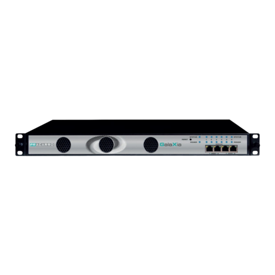
1 Chassis Overview 1.1 Front Panel GALAXIA High Density Digital Headend is a new professional High Level media platform which focuses on distribute contents on Hospitality market. With powerful embedded Gigabit switch, optional encoder modules and multi-mode receiver and modulator modules, it has been preconfigured to meet all the major video delivery requirements of signal receiving, descrambling, encoding, multiplexing, modulation and IP processing depending on a variety of models. -
Page 6: Installation
2 Installation 2.1 Rack Installation The GALAXIA HEADEND is designed to be mounted in a standard 19” rack. It takes 1RU of rack space. To install it into a rack, please use the following steps: 1. Determine the desired position in the rack for the GALAXIA HEADEND. Make sure that the air intake on the top of the unit and the exhausts on the back of the unit will not be blocked. -
Page 7: Module Overview
3 Module Overview 3.1 GALAXIA HEADEND Chassis and Baseboard (*) GALAXIA HEADEND Basic Function Up to 120 inputs & 120 outputs IP channel, dual GX-BOX-DP Chassis Baseboard power supply 3.2 Receiver Modules (*) Module Description 4 Channel DVB-C receiving and descrambling... -
Page 8: Galaxia Web Gui
GALAXIA HEADEND unit. ● Check the physical connection by ping command. GALAXIA HEADEND has an embedded gigabit switch inside the chassis. You can use it as a switch to connect other devices together. The four network ports are respectively used for management and data transmission. -
Page 9: Logging Into The Web Gui
4.1.2 Logging into the Web GUI Enter the GALAXIA HEADEND Baseboard IP address into the URL field of any recommended browsers (IE8 or later, Firefox, and Google Chrome) to access the login page. The default user name and password are both admin. Click Login to log into the GUI. -
Page 10: System Setting
Network, Time Setting, System Manage and Password. System Setting > Network In Network page you can assign a static IP address to GALAXIA HEADEND’s baseboard. Click the Apply button on the right side to make the change take effect. - Page 11 ● Manual mode System Setting > System In System page you can do an upgrade, import or export configuration, import or export license (only for baseboard), reboot the whole unit, restore it to factory setting (only for baseboard), export log and clear log (only for baseboard). System Setting >...
-
Page 12: Ip Input
System Setting > NMS Register NMS, unified network management, is a remote management tool. 4.4 IP Input Click the IP Input on the top line to go into IP input page where you can see Status, Basic Setting and Service Configuration. IP Input >... - Page 13 Click the icon ( ) in the TS Analysis list to see the TS analyzing result of this channel. Click the icon ( ) in the Service List to see the Services of each channel. ● TS Analysis Click Reset Counter button to clear continuity count errors and restart counting. Fill in the search bar with the key words of PID / Bit rate / bandwidth / table type / service name in the search bar to get the info you want.
- Page 14 IP Input > Settings Here you can configure IP input parameters: Source IP Address, Source Port, Protocol (UDP/RTP), TS Packets Per IP Packet, VLAN Enable, and TSIP Port. Click Apply to make the setting take effect. If you want to configure a batch of channels, please click “Batch Setting”. To set the IP input parameters in batch, you can check the boxes before parameters you need then choose/modify the values.
- Page 15 IP Input > Service Configuration To stream an input source, you can configure the destination in this page. ● Multiplex or Bypass stream: Click the setting icon ( ), check the output module, and then you can set the output channel of this stream. After you select bypass mode, this output channel will be occupied only by this stream and when you set other stream output channels, this channel will not be available in this time.
-
Page 16: Ip Output
After setting output destination, click Apply to make it take effect. The destination channel will be displayed in the channel/service line. And you can also click Clear Config to clear all of the configuration. There is a channel scan button ( ) on top. - Page 17 ● Multicast output setting: You should fill the fit multicast IP addresses as output in the Destination IP Address box. Please avoid IP conflict among baseboard, encoder modules (see encoder modules page) and other devices when you set the multicast output. ●...
-
Page 18: Admin
4.6 Admin Click Admin and you can choose to set password or to log out. 5 Module Configuration 5.1 Receiver Modules 5.1.1 GX-4C2CI-BP-00 GX-4C2CI-BP-00 is a 4-channel DVB-C receiving and descrambling module with 1 RF female connector and 2 CI slots. It can receive 4 RF channels signal simultaneously and support 2 CAM cards for descrambling the desired programs. - Page 19 Click TS Analysis of each channel, you can see TS Bitrate Analysis. Click Reset Counter to reset the Continuity Count Error counter. In Search bar, you can input key words or numbers, such as PIDs, Type or Service, for a quickly search. Click the icon to check service information of all the inputs.
- Page 20 GX-4C2CI-BP-00 > CI For the encrypted services received on GX-4C2CI-BP-00 module receiver, CI slot is needed to decrypt and re-broadcast the services. The GX-4C2CI-BP-00 has 2 CAM slots and can decrypt services depending on the capability of the CAM module and Smart Card. You can select the CAM Max Bit Rate from 48Mbps to 108Mbps in pull-down list depending on the total effective bitrate of services you want to decrypt and from the maximum bitrate manageable from the Professional CAM.
- Page 21 Service Configuration page is where you can manage the received services and output them to their designated interface. The configuration of all modules in GALAXIA HEADEND is mostly the same. First, you need to scan the port on each LOCKED TS. Each port might be scanned automatically or needed to be scanned manually when its source is changed.
-
Page 22: Gx-4S2Ci-Bp-01
5.1.2 GX-4S2CI-BP-01 GX-4S2CI-BP-01 is a 4-channel DVB-S/S2/S2X receiving and descrambling module with 2 RF connectors and 2 CI slots, each RF connector with 2 transponders receiving. Service configuration is very similar to GX-4C2CI-BP-00 (DVB-C receiver module). Status, CI Status and System operation, refer to GX-4C2CI-BP-00 module section. GX-4S2CI-BP-01 >... -
Page 23: Gx-4S2Fta-Bp-01
5.1.3 GX-4S2FTA-BP-01 GX-4S2FTA-BP-01 is a 4-channel DVB-S/S2/S2X FTA receiving module with 4 RF connectors and 4 LNBs that are independently powered. S2 supports up to 32APSK, S2X supports up to 64APSK. GX-4S2FTA-BP-01 > Status Click TS Analysis of each channel, you can see TS Bitrate Analysis. Click Reset Counter to reset the Continuity Count Error counter. - Page 24 GX-4S2FTA-BP-01 > Setting Channel 1.1, 1.2, 1.3 and 1.4, 4 LNBs are independently powered. Name Range Satellite Frequency (Mhz) 950 ~ 14500 Symbol Rate (KBaud) 1000 ~ 45000 LNB Frequency (Mhz) 0 ~ 13550 LNB Power Off / 13V / 18V LNB 22 Khz Off / 22 Khz The absolute value of the difference between the Satellite Frequency and the LNB Frequency...
- Page 25 GX-4S2FTA-BP-01 > Service Configuration Click the Apply or Clear Config button on the right side to make the changes made take effect or clear all configuration. ● Scanning Time (ms):1000~5000. Please try to increase this value if service name is not present, while it will slow down scanning process.
- Page 26 GX-4S2FTA-BP-01 > IP Output This feature enables you to output S2 services directly without involving baseboard processing. No baseboard resources will be consumed in this way. IP Output > Status>This page shows detailed status of each channel. The TS Analysis and Service List here have the same function to those on the Status page.
- Page 27 If you want to use IP output channels in the receiver module and baseboard IP output channel at the same time, you should avoid multicast IP address conflict. If there are two identical IP addresses enabled concurrently, both the multicast transport streams will be affected.
- Page 28 ● TS setting: Click TS line (the green area) to configure Original Network ID, TS ID and each Service ID, Service Name, and Service Provider, etc. ● NIT setting: Click the icon to modify NIT Network and NIT Stream. GX-4S2FTA-BP-01 > System On System page you can import/export License, export SNMP MIB files, Reboot module, restore factory default settings and manage logs.
- Page 29 ● Click to clear all log messages on the screen. ● Click to delete all log information. ● Click to export log information. ● Click to filter desired log messages. Clicking the filter icon, you can simply select what logs to be included.
-
Page 30: Gx-4T2Ci-Bp-00
Name Range Frequency (Khz) 47000 ~ 862000 Bandwidth (Mbps) 6 / 7 / 8 M Click the Apply button on the right side to make the change takes effect. Status, CI, Service Configuration and System, please refer to GX-4C2CI-BP-00 (DVB-C receiver module). -
Page 31: Encoder Modules
5.2 Encoder Modules 5.2.1 GX-4HDMI-BP-R01 GX-4HDMI-BP-R01 is a 4-channel HDMI input encoder which supports H.264 HD/SD or MPEG-2 SD encoding. The module supports MPEG1-L2, AAC and AC3 audio encoding. GX-4HDMI-BP-R01 > Status GX-4HDMI-BP-R01 > Basic Setting... - Page 32 Click Advanced Setting to see all parameters you can modify and check what specific parameters you want to set and see. Click the Apply button on the right side to make the change takes effect. Setting range: Video Encode Settings Range Video Encode Settings Range...
- Page 33 Audio Encode Settings Range Audio Encode Settings Range Encoding Type Audio Sampling Bitrate (Khz) MPEG1_Layer2 MPEG2_AAC MPEG4_AAC Audio Mode Audio PID 32 ~ 8190 Dual Channel Mono Stereo Encoding Bitrate (Kbps) 128 ~ 384 (AC3) Volume 0 ~ 8 64 ~ 384 (MPEG1_Layer2) 32 ~ 384 (MPEG2_AAC/ MPEG4_AAC)
- Page 34 To use Multiplexing mode on service level 1. Click on the pencil icon There will always be a Baseboard selection for the IP output and other Output options depending on the modules inserted. 2. Select the correct Output and Channel you want to output the Service to. 3.
- Page 35 LOGO Parameter Range LOGO Parameter Range Position X 0 ~ 1920 (Dual) Position Y 0 ~ 1080 (Dual) Size width 0 ~ 1920 (Dual) Size Height 0 ~ 1080 (Dual) ● OSD setting: OSD Parameter Range OSD Parameter Range Position Bottom / Top / Middle Position Offset -200 ~ 200...
- Page 36 ● QR Code setting: QR Code picture picking method is same as LOGO setting. QR Code Parameter Range QR Code Parameter Range Position X 0 ~ 1920 (Dual) Position Y 0 ~ 1080 (Dual) Size width 0 ~ 1920 (Dual) Size Height 0 ~ 1080 (Dual) GX-4HDMI-BP-R01 >...
-
Page 37: Modulation Output Modules
5.3 Modulation Output Modules 5.3.1 GX-BP-16C-R00 GX-BP-16C-R00 module supports modulating 16 non-adjacent or channels with 1 RF female port for modulating output and 1 RJ45 network port is reserved for future use. GX-BP-16C-R00 > Basic Setting This page is where you can modify or set the frequency for the RF modulation. GX-BP-16C-R00 has 16 non-adjacent channels. - Page 38 Name Range Name Range Bandwidth 6M, 7M, 8M RF Level 0 ~ 63 (dBµV) 60 ~ 123 (dBµV) Symbol Rate (KBaud) 4400 ~ 6956 Frequency (KHz) 48000 ~ 858000 PSI / SI Interval (ms) 50 ~ 10000 Constellation QAM 16 / 32 / 64 / 128 / 256 GX-BP-16C-R00 >...
- Page 39 2) Set the NIT Stream values within each single T.S. in distribution. Add Original Network ID, add TS ID and confirm with ADD operation. This operation will be performed for each T.S. distributed and visible in the section on the left side.
- Page 40 5) Set the desired LCN value and select with the check mark the programs for which you want to distribute the LCN value in the output transport stream. Confirm with OK. This operation will be performed for each T.S. distributed. 6) Select the modify menu if you wish to check or modify the previously set LCN values.
-
Page 41: Gx-Bp-8T-R01A
5.3.2 GX-BP-8T-R01A GX-BP-8T-R01A module supports up to 8 adjacent frequencies modulating with 1 RF female connector for output. Module configuration is similar to IP Setting. GX-BP-8T-R01A > Basic Setting Click the Apply button on the right side to make the change takes effect. Name Range Name... - Page 42 GX-BP-8T-R01A > Output In the OUTPUT menu of the module to be configured, all the programs grouped by T.S. (Tranport Stream) value will be displayed. See following image. 1) Set the Original Network ID value compliant with the value used in the country of use of the control panel and a unique TS ID value for each T.S.
- Page 43 This operation will be performed for each T.S. distributed and visible in the section on the left side. 3) Select Descriptors 4) Select Logical Channel Number 5) Set the desired LCN value and select with the check mark the programs for which you want to distribute the LCN value in the output transport stream.
- Page 44 This operation will be performed for each T.S. distributed. 6) Select the modify menu if you wish to check or modify the previously set LCN values. This operation will be carried out if necessary for each T.S. Distributed.
-
Page 45: Function Modules
5.4 Function Modules 5.4.1 GX-2CI-BP-00 GX-2CI-BP-00 is a descrambling module with 2 CI slots. It supports almost all kinds of CAM card descrambling and the number of descrambled services is defined by the CAM card. It supports descrambling services which are multiplexed from different IP/RF channels or modules. - Page 46 GX-2CI-BP-00 > CI CI page not only shows the CAM card name and CA system ID, but also shows the service PID, service information and descrambling status. CAM Max Bitrate is from 48Mbps to 108Mbps, which you can choose in the pull-down list. Click Reset to reboot the CAM card.
- Page 47 GX-2CI-BP-00 > Service Configuration When this module is licensed to scramble, on this page, you can set the output destination of all services. When this module is licensed to descramble, on this page, you can select the descrambled services and set the output destination of all services. Click the Apply button on the right side to make the change takes effect.
- Page 48 GX-2CI-BP-00 > System On System page you can import/export License, Reboot module, Factory Reset and manage Logs. ● Turn on Enable Real-time Log switch to see the real time log message and the security level of each message below. ● Click to clear all log messages on the screen.
-
Page 49: Appendices
6 Appendices Appendix A - Abbreviations 8VSB Vestigial sideband modulation with 8 discrete amplitude levels 16VSB Vestigial sideband modulation with 16 discrete amplitude levels Advanced Audio Coding AC-3 Also know as Dolby Digital Asynchronous Serial Interface ATSC Advanced Television Systems Committee Audio Video Bouquet Association Table Bit Error Ratio... - Page 50 Local Oscillator Mbps 1,000,000 bits per second Modulation Error Ratio Management Information Base MPTS Multi-program Transport Stream Network Information Table OFDM Orthogonal Frequency Division Multiplexing Program Association Table Program Clock Reference Packet Identifier Program Map Table Program Specific Information Power Supply Unit Quadrature Amplitude Modulation QPSK Quadrature Phase Shift Keying...
- Page 51 SAFETY WARNINGS The product can only be installed by qualified personnel in compliance with local safety laws and regulations. Fracarro Radioindustrie is free from all civil and criminal responsibility due to breaches of current legislation derived from the improper use of the product by the installer, user or third parties.
Need help?
Do you have a question about the GALAXIA and is the answer not in the manual?
Questions and answers