
Related Manuals for Turtle Tough 6000 Series


Summary of Contents for Turtle Tough 6000 Series
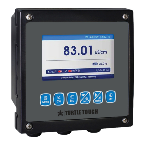
- Page 1 TURTLE ® TOUGH MANUAL 6000 SERIES DIGITAL SMART ANALYSERS Conductivity Resistivity/Salinity TURTLE ® turtletoughsensors.com TOUGH...
- Page 2 Turtle Tough Sensor. This instruction manual provides information for the correct installation and use of a Turtle Tough 6000 Series Digital Smart Analyser, to ensure you get the maximum life and performance from your sensor. Any use other than the one described here compromises the safety of persons and the entire measuring system and is, there- fore, not permitted.
-
Page 3: Installation
Installation As with all instrumentation, the installation and commissioning of this instrument are crucial to its Danger safe and effective operation. This instrument must only be used for its purpose as outlined in this Electric manual. It must be installed and commissioned by this manual and by trained, qualified personnel. Shock Hazard Site Selection... -
Page 4: Specifications
Specifications Product Name 6000 Series Samrt Digital Analyser Conductivity 0~500mS/cm Resolution 0.1us/cm;0.01ms/cm Intrinsic Error ±0.5%F.S Resistivity 0~18.25MΩ/cm Resolution 0.01KΩ/cm;0.01MΩ/cm 0~250g/L Resolution 0.01mg/L;0.01g/L Salinity 0~700ppt Resolution 0.01ppm;0.01ppt Temperature -10 to 150 °C Resolution ±0.3 °C Temperature Compensation Automatic or manual Power Supply... - Page 5 Installation Dimensions 118 mm 144 mm 26 mm M4x4 45x45 mm 138 mm +0.5 mm Back fixed hole size Embedded mounting Cut-out size TURTLE ® TOUGH...
-
Page 6: Embedded Installation
Installation Embedded Installation Install fixing bracket for instrument Insert into the cut-out hole D+ D- Installation completion diagram Wall Mounted Installation 150.3 mm 6x15 mm Installation completion diagram Install fixing bracket for instrument Wall screw fixing Install fixed bracket top view, pay attention to TURTLE ®... -
Page 7: Wiring Connection
Wiring Connection V+,V-,A1,B1 Digital Input Channel 1 REF1 PH/Ion reference 1 V+,V-,A2,B2 Digital Input Channel 2 INPUT1 PH/Ion measure 1 I 1,G,I 2 Output current TEMP1 Temperature 1 A3,B3 RS485 communication output SEN-,SEN+ Membrane dissolution of oxygen/FCL G,TX,RX RS232 communication output P+,P- VDC power supply REF2... - Page 8 Navigation Keypad Operation Short Press: Release the key immediately after pressing. ((Default to short presses if not indicated below) Long Press: Press the button for 3 seconds and then release it. Press & Hold: Press the button and accelerate after a certain time until the data is adjusted to the required value before releasing the button.
- Page 9 Display Before using please check all pipes and electrical connections. After power supply, the analyser is shown as: Measurement Mode Setting Mode Calibration Mode Trend Chart Display TURTLE ® TOUGH...
-
Page 10: Menu Structure
Menu Structure Electrode Type Setting Salinity Resistivity us/cm, ms/cm Electrode Set KΩ/cm, MΩ/cm Unit Setup mg/L, g/L ppm, ppt Electrode Constant 1.0 (Default, can be modified) Setting Temperature Coefficient 2.0 (Default, can be modified) NTC2.252 kΩ NTC10 kΩ Temperature Sensor Pt100 Pt1000 Temperature... - Page 11 Main Channel Temperature 4-20 mA Current 1 Output Option 0-20 mA 20-4 mA Upper Limit Lower Limit Main Channel Temperature 4-20 mA Current 2 Output Option 0-20 mA Output 20-4 mA Upper Limit Lower Limit 4800 BPS Baud Rate 9600 BPS 19200 BPS None RS485...
-
Page 12: Field Calibration
Calibration Press [MENU] to enter the setting mode and select the calibration. Calibration Point 1 Enter given standard liquid value (Example:0.01) Calibration Point 2 Enter given standard liquid value (Example:84us/cm) Standard Solution Calibration Calibration Point 3 Enter given standard liquid value (Example:1413us/cm) Calibration Point 4 Enter given standard liquid value (Example:84ms/cm) Calibration... - Page 13 Graphic Trend(Trend Chart) Press [MENU] to enter the setting mode and set the record interval. The analyser will save the data according to the selected record interval. Interval/Point 400 points per screen, Displays most recent data trend 1h/Point 400 points per screen. Data trend chart display of the last 16 days Curve Query (Trend Chart) 12h/Point 400 points per screen.
-
Page 14: Command Structure
Modbus RTU General Information The hardware version number of this document is V2.0; the software version number is V5.9 and above. This document describes the Modbus RTU interface in details and the target object is a software programmer. Modbus Command Structure Data format description in this document;... - Page 15 Modbus RTU Transmission Mode When the instrument uses RTU (Remote Terminal Unit) mode for Modbus serial communication, each 8-bit byte of information contains two 4-bit hexadecimal characters. The main advantages of this mode are greater character density and better data throughput than the ASCII mode with the same baud rate. Each message must be transmitted as a continuous string.
- Page 16 Modbus RTU CRC Check The RTU mode contains an error-detection domain based on a cyclic redundancy check (CRC) algorithm that performs on all message contents. The CRC domain checks the contents of the entire message and performs this check regardless of whether the message has a random parity check. The CRC domain contains a 16-bit value consisting of two 8-bit bytes.
- Page 17 The following illustrates the request frame and response frame with the read and hold register 108-110 as an example. (The contents of register 108 are read-only, with two byte values of 0X022B, and the contents of register 109-110 are 0X0000 and 0X0064) Request Frame Response Frame Number Systems...
- Page 18 Data Format In Instrument Floating Point Definition: Floating point, conforming to IEEE 754 (single precision) Description Symbol Index Mantissa 30...23 22...0 22...0 Index Deviation Figure 14: Floating point single-precision definition (4 bytes, 2 Modbus registers) Example: Compile Decimal 17.625 to Binary •...
- Page 19 If it is large-end storage mode, after executing the above statement, the data stored in outdata of address unit is 0x41 address unit (outdata + 1) stores data as 0x8D address unit (outdata + 2) stores data as 0x00 address unit (outdata + 3) stores data as 0x00 2.
- Page 20 Function description: parameters byte0, byte1, byte2, byte3 represent 4 bytes of binary floating point number ( the return value Converted the decimal number For example, the user sends the command to get the temperature value and dissolved oxygen value to the probe. The 4 bytes representing the temperature value in the received response frame are 0x00, 0x00, 0x8d and 0x41.
-
Page 21: Product Warranty
Shelf Life Warranty The standard shelf life for a Turtle Tough sensor is one year from the date of shipment. Sensors stored longer than this period may still be functional but are no longer under warranty. Sensors should be stored in a cool, dry location with the sensor tip (where the pH/ORP element is located) oriented toward the ground. - Page 22 IMPORTANT: Ground loops, poor earthing and faulty electrical installations are a common cause of sensor damage. If you are experiencing unusual or erratic readings, please refer to our support document on ground loops. Damage to Cables and Connectors Please note that integral sensor cables, connectors and plugs must NOT be cut, removed or modified in any way. Sensors contain sensitive internal electronics and our cables and connectors are designed to protect the integrity of these components.
-
Page 23: Troubleshooting
Troubleshooting PROBLEM POSSIBLE CAUSES SOLUTION Check whether the power supply is connected or not, and check whether the power supply LCD display is not bright Instrument or LCD Screen power supply failure wire of the sensor is connected in the wrong direction Check that the current output wiring is correct.
Need help?
Do you have a question about the 6000 Series and is the answer not in the manual?
Questions and answers