
Related Manuals for Turtle Tough TT-ISE-CL2


Summary of Contents for Turtle Tough TT-ISE-CL2
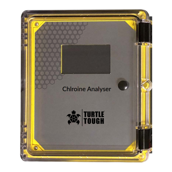
- Page 1 TURTLE ® TOUGH MANUAL TT-ISE-CL2 ANALYSER Reagentless Amperometric Free or Total Chlorine Residual Analyser Chlroine Analyser TURTLE ® turtletoughsensors.com TOUGH...
- Page 2 TURTLE ® TOUGH...
- Page 3 Maintenance Cleaning The Electrode Finger Tip Parts List Sensor Maintenance, Storage Warranty 3 System Component Identification and Description Return Goods Model TT-ISE-CL2 Specifications Support Analyser Component Identification and Description Main Circuit Board Component Identification Installation Sample Point Selection Guidelines Unpacking...
- Page 4 policyTurtle Tough ...
- Page 5 analyser The Turtle Tough model TT-ISE-CL2 uses a membrane covered amperometric sensor to. continuously monitor and control free or total residual chlorine without any reagents or moving parts. The difference between the two models is the type of sensor used and corresponding measurement it produces, free or total chlorine.
- Page 6 analyser NOTE: Using the sensor without mounting it in the supplied flow cell will lead to incorrect measurement results; it cannot simply be submerged in a pipe, basin, channel or tank. analyser If no chlorine is to be measured for over 24 hours the sensor must be disconnected from the analyser, the membrane cap emptied, rinsed and the sensor stored per instructions.
- Page 7 Contaminant Secondary MCL Aluminum 0.05 to 0.2 mg/L Chloride 250 mg/L Color 15 color units Copper 1.0 mg/L Corrosivity Non-corrosive Fluoride 2.0 mg/L Foaming agents 0.5 mg/L Iron 0.3 mg/L Manganese 0.05 mg/L 6.5 - 8.5 Silver 0.1 mg/L Sulfate...
- Page 8 2 & 3-Electrode Free Chlorine Sensor Description The 2 or 3-electrode membrane-covered, amperometric sensors are used to measure the concentration of free chlorine in drinking and swimming pool water, industrial, process and cooling water. The following inorganic chlorinating agents can be measured with the sensor for free chlorine: chlorine gas (Cl2), electrolytically generated chlorine, sodium hypochlorite (NaOCl, chlorine bleach lye), calcium hypochlorite (Ca(OCl)2) or chlorinated lime (Ca(OCl)Cl).
- Page 9 As there must be an electrical connection between the counter electrode and the measurement medium, the measurement medium must have a minimum conductivity of approx. 10 µ S/cm. This means that the sensors are not suitable for use in highly-purified water, or similar. 2-Electrode Free Chlorine Sensor Description The sensor for free chlorine is a potentiostatic 2-electrode sensor with a micro porous, Hydrophobic (moisture repellent) PTFE membrane and special electrolyte.
- Page 10 Details Total Chlorine Sensor and 3-Electrode Free Chlorine Sensor (14) (10) (13) (11) (12) Cable gland nut Terminal Cover O-ring 2-pin terminal for measuring cable connection Electrode shaft with integrated electronics Counter electrode (stainless steel) ...
- Page 11 Details 2-Electrode Free Chlorine Sensor (12) (11) (10) Cable gland nut Terminal Cover O-ring 2-pin terminal for measuring cable connection Electrode shaft with integrated electronics O-ring Electrode finger (reference electrode) Measurement electrode Transparent vent seal (10) Membrane cap (11) PTFE membrane (12) Vent hole ...
- Page 12 Specifications, Total Chlorine Sensor Analyte Total chlorine Membrane type Hydrophilic membrane 2-pin terminal, polyamide PG7 screw connection; Measuring cable wire cross section 2x 0.25mm 2 , cable diameter approx. 4 mm connection Voltage supply U B 12 to 30 V DC (electrical isolation recommended) Electromagnetic According to EN 61326-1 compatibility...
- Page 13 Free Chlorine Sensor Data, 2 -Electrode & 3-Electrode with Reduced pH Dependence Analyte Membrane type Hydrophobic PTFE membrane Hydrophilic membrane 2-pin terminal, polyamide PG7 screw connection; Measuring cable wire cross section 2x 0.25mm 2 , cable diameter approx. 4 mm connection Suitable chlorination agents Inorganic chlorine compounds: NaOCl (sodium hypochlorite), Ca(OCl)2,...
- Page 14 The flow cell (part no. 303500) is fastened to a wall or mounting panel with mounting bracket (part no. 303501) Sensor Mounting bracket (303501) Connection G1/4 for hose ø 8mm x 6mm Flow cell housing ...
- Page 15 (10) Sensor Inspection glass Union nut Inlet G1/4A or DN10 Flow Cell Stepped collar 1" Outlet G1/4A or DN10 Compression ring (10) O-ring, stepped O-ring, inspection glass collar Part of the flow cell. The transparent inspection glass (6) can be unscrewed from the fitting housing for cleaning. ...
- Page 16 The electrolyte will come out of the valve opening when the membrane cap is screwed on. Wear safety goggles and gloves. Wash off electrolyte (an aqueous solution of an alkali halide) under flowing water. NEVER SCREW THE MEMBRANE CAP ON OR OFF WITHOUT FIRST MOVING THE VENT SEAL AWAY FROM THE VENT HOLE.
- Page 17 To avoid forming bubbles do not shake the electrolyte. Make sure the vent hole is open. Tilt the electrolyte bottle as shown to minimize bubbles and fill the membrane cap up to the brim with electrolyte, if needed tap to eliminate bubbles.
- Page 18 After tightening the membrane cap, slide the vent seal up into the groove, so that it covers the vent hole. Rub around the vent seal to remove any bubbles or voids. If liquid leaks through the membrane, the membrane is faulty and you must use a new membrane cap.
- Page 19 Install the Sensor Insert the sensor into the flow cell with the wiring terminals facing you. Slide the union nut over the sensor and tighten onto the flow cell. Slide the cable gland nut and terminal cover over the sensor cable in the order shown.
- Page 20 Screw the terminal cover onto the sensor and then tighten the cable gland nut. The solution ground pin on the front of the flow cell is normally not needed, it may be used if you find a solution ground is necessary. ...
- Page 21 Cleaning the electrode finger (3,4) incorrectly may damage the sensor. Do not sand the brown coating on the combined counter and reference electrode (3). Do not touch or contaminate the electrode finger (3,4). Carry out the following steps exactly as they are described. ...
- Page 22 The service life of the electrolyte is 3 to 6 months. The service life of the membrane depends on the water quality. If the sensor still indicates values that are too low after the electrode finger tip has been cleaned, a new membrane cap must be used.
- Page 23 TT-ISE-CL2 General Product Description Amperometric reagentless total chlorine residual analyser Intended Use Continuous monitoring and control of chlorine residual prior to dechlorination Measurement Method Amperometric potentiostatic membrane covered 3-electrode Parameters Measured Total (combined) residual chlorine Available Operating Ranges 0-0.5 mg/l to 0-20 mg/l (ppm) °C...
- Page 24 Analyser Analyser Chlorine Analyser Sample inlet, 2-way ball valve Flow Cell Sensor Flow meter with valve, 12 GPH Pressure regulator with gauge Drain tubing Sample tap tubing Analyser electronics 5 Amp fused power input module 24VDC power supply, 88-264 Volts AC, 50/60 Hz. Input ...
- Page 25 Touch screen display connection screen display connection Chlorine sensor connection mA output (only one output is output is active) Power input module Power supply (under main circuit board Power supply (under main circuit board, not shown, see previous page) 1Amp Hi &...
- Page 26 The sample must be taken at a point after the chlorine has been thoroughly mixed and has had time to react completely with the process water. A sample point that is too close to the chorine injection point will deliver a sample that is not mixed adequately or has not had sufficient time to complete the chemical reaction, thereby producing inaccurate readings.
- Page 27 The TT-ISE-CL2 chlorine analyser is shipped with two serial number labels found on the bottom right side of the enclosure, and on the inside of the enclosure door. The labels include the factory calibrated chlorine residual range. Should technical assistance be required, refer to the serial number to identify your system.
- Page 28 analyser Locate at approximate shoulder height for convenience. The TT-ISE-CL2 should be level from side to side and front to back. 1. Attach the four mounting feet to the rear of the electronics enclosure using the included 5/16"-18 x 1/2" flat head screws.
- Page 29 CAUTION: the printed circuit board is sensitive to Electro CAUTION: the printed circuit board is sensitive to Electro-Static Static Discharge. It can be irreparably Discharge. It can be irreparably damaged by static electricity, causing partial damaged by static electricity, causing partial or total operational failure.
- Page 30 1A Relays NO / NC, with LED circled Processor "heartbeat" flashing LED indicator pH input Program / Run switch, factory use only Temperature input Programming input connector, factory use only 4-20mA outputs, 1 active Reset switch, factory use only Jumper, Free / Total chlorine sensor, Motor start / stop factory use only...
- Page 31 TB9 +24 Blue with white dots TB9 1 White with blue dots Shield (clear) TB9 COM Blue (-) TB2-4 White Blue Dots TB2-3 White Red Dots TB2-2 Orange (+) TB2-1 + 24V TB-2 - Gnd TB-1...
- Page 32 Disinfectant ( TB11-1 Disinfectant ( TB11-5 pH ( TB11-2 pH ( TB11-6 Temperature ( TB11-3 Temperature TB11-7 Spare ( ) TB11-4 Spare TB11-8 TB 1-1 TB 1-2 High Disinfectant - fixed/dedicated Relay 1 Low Disinfectant - fixed/dedicated Relay 2...
- Page 33 Make sure the sample inlet ball valve is closed, the flow meter valve is closed and the drain valve is open. The pressure regulator is set to 15 PSI at the factory. Turn on the analyser by pressing the off/on rocker switch located on the bottom right underside surface of the analyser enclosure.
- Page 34 analyser TURTLE ® TOUGH...
- Page 35 analyser ...
- Page 36 MAIN RANGE ALARMS CALIBRATION SETTINGS pH Mode Span Set High Alarm Set Low Alarm Set Chlorine Zero Screen Settings Man/Auto Low Alarm Screen High Alarm Chlorine Delay Standard Delay Brightness Volume TURTLE ® TOUGH...
- Page 37 Navigation through the menus is done simply by touching the item of interest. After performing an adjustment you will return to the main home screen by touching menu. You will find that lightly tapping with your fingernail works the best. You will hear a beep when a selection is made. Touching the Menu button will display the main submenus available to configure the analyser.
- Page 38 Setting the operating range will automatically set the mA output of the disinfectant residual to match the operating range, set the high alarm to 90% of span, and low alarm to 10% of span. The alarms can later be configured as needed. The range must match the operating range of the sensor. To change the operating range you must purchase a sensor with a different operating range.
- Page 39 There are a total of (8) 1A dry contact form C relays each with LED indicator installed on the circuit board, only (3) are active in the standard configuration. Relay 1 is dedicated to the High disinfectant alarm, Relay 2 for the Low disinfectant alarm, and Relay 3 for the No Flow alarm. Upon a relay energizing its LED indicator will light.
- Page 40 The accuracy of the TT-ISE-CL2 can never be greater than the instrument it is being calibrated against. Accuracy is a function of the method used, inherent tolerances in the calibration instrument, the quality and freshness of reagents, and the care taken to perform the calibration.
- Page 41 A zero-point calibration is not required for the chlorine sensors included. If there is no chlorine present in the process medium, approximately zero is indicated. The zero point is independent of changes in the flow rate, conductivity, temperature and pH value. If needed, the zero point can be re-set electrically.
- Page 42 The settings screen allows you to adjust pump motor speed (on vinegar buffered systems only) as well as the screen brightness and audio volume. This screen also contains the serial number, the software version number, and display version number. These numbers are required for customer service and technical support.
- Page 43 Output signal of the sensor is Incorrect calibration Repeat calibration Calibrate the sensor more too low or too high according frequently if required Sensor output signal is too Settling time too short. Wait at least 2 hours low.
- Page 44 Sensor is unusually slow in The membrane is partially Replace membrane cap. Take steps to improve the responding blocked by pollutants water quality. such as calcium or oil. Disinfectant is prevented from reaching the sensor Output signal of the sensor The sensor has been Connect the sensor...
- Page 45 1. Unscrew the membrane cap per procedures. 2. Carefully rinse the electrode finger and dry it carefully with a clean cloth. 3. Connect the sensor to the indicator/controller and wait for approx. 5 minutes. 4. Read the signal from the cell on the analyser or measure it with a digital multimeter. The measured value should be approx.
- Page 46 The TT-ISE-CL2 analyser is designed to operate continuously, 24 hours a day, 365 days a year. The system requires little routine maintenance other than changing the sensor electrolyte at prescribed intervals and mandated calibration checks. However, regular maintenance should be performed to ensure optimum performance and accuracy.
- Page 47 Description Part No. Touch Screen Display 400001 Display Cable 400002 Circuit Board 400003 Power Supply 400004 Power Cable 400005 6A fuse, power entry module 400008 Flow cell, single sensor 303500 Wall mount bracket, Stainless Steel, for single sensor flow cell 303515 Additional tubing flexible PVC, per foot 303526...
- Page 48 • The complete product is returned to Turtle Tough or one of its authorised service agents, in person or freight pre-paid by you, and found, on examination, to be suffering from a manufacturing defect.
- Page 49 IMPORTANT: Ground loops, poor earthing and faulty electrical installations are a common cause of sensor damage. If you are experiencing unusual or erratic readings, please refer to our support document on ground loops. Damage to Cables and Connectors Please note that integral sensor cables, connectors and plugs must NOT be cut, removed or modified in any way. Sensors contain sensitive internal electronics and our cables and connectors are designed to protect the integrity of these components.
- Page 50 Return Goods For all return goods the following information must be included in the letter accompanying the returned goods: • Model Code and Serial Number • Original Purchase Order and Date • Length of time in service and description of the process •...
- Page 51 3rd party hardware includes any device or component not supplied by Turtle Tough and can include, but is not limited to, PLC’s, SCADA systems, DCS’s, data loggers, power supplies/isolators, or any other externally sourced interfacing device or component. We suggest...
Need help?
Do you have a question about the TT-ISE-CL2 and is the answer not in the manual?
Questions and answers