Table of Contents
Advertisement
Quick Links
Advertisement
Table of Contents

Subscribe to Our Youtube Channel
Related Manuals for Red Seal Measurement neptune MP


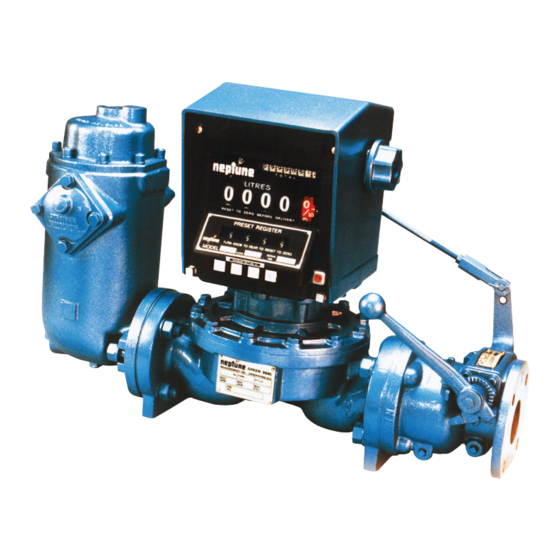
Summary of Contents for Red Seal Measurement neptune MP
- Page 1 Sold & Serviced By: Don Johns, Inc. M-150 701 N. Raddant Rd. Rev. D Batavia, IL 60510 MP Oscillating Piston Flowmeters: Ph: (630) 454-4700 1/2” Type MP www.donjohns.com 1” Type MP 2” Type MP 3” Type MP Operating and Maintenance Manual for MP Oscillating Piston Flowmeter...
-
Page 3: Table Of Contents
TABLE OF CONTENTS DESCRIPTION PAGE General Information ..................1 Installation ....................1 Calibration .......................2 Register Maintenance..................3 Pulsmate Electronic Register ................3 800 Series Register ..................4 1” MP w/Double Trip Auto-Stop Valve .............5 2” MP w/Single Trip & Double Trip Auto-Stop Valve ........6-8 3”... -
Page 5: General Information
1/2”, 1”, 2” AND 3” MP FLOWMETERS GENERAL INFORMATION GENERAL MAINTENANCE This manual is intended to be a guide for the proper operation and maintenance of the 1/2”, 1”, 2” and 3” MP Flowmeters and accessories, as described in Form TS-150. -
Page 6: Calibration
When Installing Secure the connecting piping firmly to prevent strain on the flowmeter casing. Use self-aligning couplings and expansion joints in long piping runs to allow for expansion and contraction caused by temperature changes. Provide the metering system with means for pressure and relief or escape of trapped liquid caused by temperature expansion. -
Page 7: Register Maintenance
REGISTER MAINTENANCE REGISTER MAINTENANCE Register parts are such that only minor field repairs are advisable. When a register is in need of extensive service or repair other than that for which instruction is given here, it is recommended that the register be returned to the nearest RSM distributor for repair. -
Page 8: 800 Series Register
800 SERIES REGISTER 800 SERIES REGISTER To Remove Register From Loosen the two clamp screws on lower front of the register. Lift the register off. On Flowmeter Auto-Stop models the valve linkage must first be disconnected. (Remove cotter pin and washer at valve end.) When one register is removed and another substituted, (1) Check the number of teeth on the change gears. -
Page 9: 1" Mp W/Double Trip Auto-Stop Valve
Remove cotter pins (E) from valve linkage. Unscrew the outside register link lock nut (P) and remove connecting rod (G). Remove register link (N), rotate 1/2 turn and reassemble onto register as described in appropriate valve adjustment instructions (Page 6). Loosen two clamp screws on lower front of register up and turn register 180º. -
Page 10: 2" Mp W/Single Trip & Double Trip Auto-Stop Valve
It is sometimes necessary to change the position of the handle. This can be done by loosening handle screw (B) and repositioning the handle as follows: If the register mechanism will not latch up, position the handle further toward the register. If the valve will not close, the handle may be positioned away from the register. - Page 11 Remove valve handle stop set screw (B) and screw into holes on opposite side of valve. Adjustment of Auto-Stop Valve After completing the above instructions, the valve linkage must be adjusted in accordance with the procedure, for the specific type valve (i.e. Double Trip or Single Trip) as outlined on pages 7 &...
- Page 12 Figure 4 Note: If it is difficult to obtain proper rate of flow during intermediate trip position and still have register latch up fully, check Auto-Stop valve to ensure that it is opening all the way. Check valve by removing set screw (B) and clevis (F) from valve arm; open valve as far as possible.
-
Page 13: 3" Mp
Figure 5 TO ROTATE THE REGISTER TO ROTATE THE REGISTER (3” MP) Remove the register from the flowmeter. Two studs and two threaded holes will Non Preset Models be seen on the top of the gear train. To turn the register 90º transfer the studs to the empty holes. - Page 14 Check engagement of connecting rod in clevis; tis should be approximately 1”. Attach connecting rod; do not tighten the nuts at “F.” 10. Turn connecting link arm on register to its maximum counter-clockwise, full latched open position. Hold valve open and tighten two nuts at “F” on connecting rod.
- Page 15 Registers are shipped from the factory with the Preset mechanism adjusted to trip To Adjust the Tripping Point correctly at the normal rates of flow. If due to a change in the speed of closing of the valve or for any reasons the Preset does not trip off at the correct point, the trip point may be adjusted as follows: If the valve is closing “off the mark,”...
- Page 16 OPERATION OPERATION With the main valve and the pilot valve closed, the inlet pressure and the spring keep the valve closed. To open the valve, the handle is lifted, lifting the pilot valve off its seat. Inlet pressure within the cylinder is dissipated through the pilot valve to the outlet, so that a difference in pressure exists between top and bottom of the piston.
- Page 17 To disassemble valve, remove cover (43) from end of valve. (Refer to To Disassemble Valve figure 9). Remove cylinder retaining screw (25), seal screw (28) and needle valve (27). Using a 5/8” bolt, screwed loosely into tapped hole in end of cylinder (38), pull cylinder and piston assembly through end of valve body.
-
Page 18: 600 Series Register
If Leakage Occurs Around This may be caused by worn “O” ring (19). To replace, remove screw (10), Valve Shaft connecting rod arm, handle and stop plate (14). Then knock out drive pin (15). In doing this be sure that shaft is supported so that it will not be bent. Remove four screws and pull out shaft bearing bracket (20.1). -
Page 19: Operational Checks
Remove reset knob screw (#3) and four screws on bottom plate (#4). Pull out on reset knob to disengage knob from shaft. Loosen and slide housing to knob end and remove. Caution is advised in removal of housing to avoid scraping visible wheels. Reset shaft can be turned to normal position. -
Page 20: Cleaning The Flowmeter
Replacement gear trains and related parts should be ordered from the parts list, for P150. CLEANING THE FLOWMETER CLEANING THE FLOWMETER Due to the simple design of this flowmeter, there are very few internal parts to the To Clean Measuring flowmeter. -
Page 21: General Maintenance
GENERAL MAINTENANCE GENERAL MAINTENANCE To maintain accuracy of RSM MP Flowmeters, little is necessary other than to see that the proper conditions of operation are observed. Once the flowmeter has been installed correctly, these conditions consist merely in guarding against foreign matter, such as air or sediment entering the flowmeter. -
Page 22: Troubleshooting
TROUBLESHOOTING TROUBLESHOOTING Register Not Working When Liquid is Flowing Bypass around flowmeter not shut off. Frozen condensation inside register. Register in need of repair. Sheared key on change gear. Defective magnetic drive assembly. Chronic Leakage at the Main Case “O” -Ring Pump bypass stuck open. - Page 23 DIMENSIONAL DATA SIZE 1/2” 1/2” TYPE MP PULSMATE Page 19...
- Page 24 DIMENSIONAL DATA SIZE 1” 1” Type MP with 600 Series Register and Model 45 Pulse Transmitter 1” Type MP with 800 Series Register...
- Page 25 1” Type MP with 800 Series Register and Auto-Stop Valve DIMENSIONAL DATA SIZE 2” 2” Type MP with 600 Series Register and Model 45 Pulse Transmitter...
- Page 26 2” Type MP with 800 Series Register and Air/Release Strainer 2” Type MP with 800 Series Register and Auto-Stop Valve...
- Page 27 DIMENSIONAL DATA SIZE 3” 3” Type MP with 600 Series Register 3” Type MP with 800 Series Register...
- Page 28 Sold & Serviced By: Don Johns, Inc. 701 N. Raddant Rd. Batavia, IL 60510 Ph: (630) 454-4700 Fax: (630) 454-4429 www.donjohns.com © 2013 Red Seal Measurement 01/13 Speci ications subject to change without prior noti ication.
Need help?
Do you have a question about the neptune MP and is the answer not in the manual?
Questions and answers