Table of Contents
Advertisement
Quick Links
IMPORTANT: To ensure proper installation of this product, thoroughly review the information in this
revision of the manual. Information is subject to change as new features are implemented. Failure to
follow instructions may result in system malfunction.
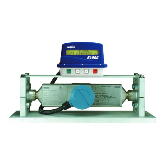
Neptune RML2000
Mass Flowmeter
www.redsealmeasurement.com
Installation Manual
M-614(I)
RML2000
Advertisement
Table of Contents

Related Manuals for Red Seal Measurement Neptune RML2000


Summary of Contents for Red Seal Measurement Neptune RML2000
- Page 1 M-614(I) RML2000 Neptune RML2000 Mass Flowmeter Installation Manual IMPORTANT: To ensure proper installation of this product, thoroughly review the information in this revision of the manual. Information is subject to change as new features are implemented. Failure to follow instructions may result in system malfunction.
- Page 2 WARNINGS, CAUTIONS AND NOTES Throughout this manual you will see WARNINGS, CAUTIONS and NOTES. They are here for your benefit and warrant attention. By paying careful attention to them you can prevent injury and possible equipment damage. Below are examples: WARNINGS: INFORM THE READER OF POSSIBLE BODILY INJURY IF PROCEDURES ARE NOT FOLLOWED EXACTLY.
- Page 3 ATTENTION - OBSERVE PRE- CAUTIONS FOR HANDLING ELECTROSTATIC SENSITIVE DEVICES. Caution - This electronic device is sensitive to damage from ESD (electro- static discharge). Observe the following precautions when servicing this device. 1. Always use a static-dissipative wrist strap. Connect the strap to a grounded, conduc- tive surface or to the metal chassis of the equipment under repair.
- Page 5 Link 3 for zeroing and configuration. ProLink 3 is compatible with all earlier releases of RML lectronics, and will be the version used and supported by Red Seal Measurement for all RML Series meters. ProLink 3 can be downloaded at www.redsealmeasurement.com/prolink.
- Page 6 Installation and Zeroing 1. Power and Data Connections 1.2. Modbus Units (800 Series Core Processor) Remove the four screws that attach the housing cover and remove the cover. Make connections to the core proces- sor as shown below.
- Page 7 1.2. Pulse Output Units (2400S Core Processor) Remove the four screws that attach the housing cover and remove the cover. The 2400s requires the upper disc to be removed before power or pulse connections can be made to the electronics. Loosen the two Philips screws on the disc and pull disc straight up.
- Page 8 2. Zeroing the meter Before performing the zeroing procedure: 1. Power the meter for at least 30 minutes to warm up the electronics. 2. Circulate product thru the meter for 5 – 10 minutes to remove vapor and allow meter to reach a steady tempera- ture.
- Page 9 2.2 Pulse Output Units (continued) Using ProLink 3: To communicate with the unit via the ProLink 3 configuration program, connect the RS-485 adapter to the A & B ter- minals of the service port (labeled SP). Then follow the instructions for “Using Prolink 3” in Section 2, Modbus Units.
-
Page 10: Table Of Contents
Table of Contents 0. AMMENDED PROCEDURES FOR NEW ELECTRONICS 1. FUNCTIONAL OVERVIEW 2. SPECIFICATIONS AND APPROVALS 2.1 RML2000 Specifications 2.2. E4000 Specifications 2.3. Custody Transfer Approval 2.4. Safety Approvals 3. SYSTEM COMPONENTS 3.1. RML2000 Coriolis Mass Flowmeter 3.2. E4000 Register Head 3.3. - Page 11 4.9 Installing the Single Stage LPG Solenoid Valve 4.10 Wiring the Single Stage LPG Solenoid Valve 4.12 Wiring the Dual Stage LPG Valve 4.11 Installing the Dual-Stage LPG Valve 4.13 Installing the Junction Box and Printer 4.14 Wiring the E4000 Register Head 4.15 Wiring the Junction Box 4.15 Wiring the RML2000 Meter to the E4000 Register 4.16 Installing the Printer...
-
Page 12: Functional Overview
1. FUNCTIONAL OVERVIEW The RML2000 Coriolis metering system for LP gas delivery trucks consists of two main elements: • The RML2000 Coriolis mass meter complete with vapor release and differential valve • The E4000 Electronic Register system The Coriolis meter is a true mass flow meter in that it directly measures the mass flow rate of the product passing through the sensor. -
Page 13: Specifications And Approvals
2. SPECIFICATIONS AND APPROVALS 2.1 RML2000 Specifications Device Type: • 1” Coriolis Mass Flow Transducer Wetted Parts: • 316L Stainless Steel Sensor Housing: • 304L Stainless Steel Line Size: • 2” (51mm) Flowrate: • NCWM Approved Volumetric Flowrate 8-82 GPM Weight: •... -
Page 14: E4000 Specifications
2.2. E4000 Specifications Display • 143 x 19 mm text area • 2 lines, 20 characters per line • 8.3 x 5.9 mm character area Power Rating (supply from isolating or battery source) • 9-16 VDC, 14.6 VDC nominal • 0.25 Amps (0.63 Amps with optional display heater) Relay Rating •... -
Page 15: Custody Transfer Approval
Printer • Epson TM-U295 Dot Matrix (Can also be used with Blaster printer) • Ticket Type: Blank / Pre-Printed up to 3 ply • Ticket Size: 102 mm x 257 mm (4 x 10”) • Power: 24 VDC +/- 2.4 VDC •... -
Page 16: System Components
3. SYSTEM COMPONENTS 3.1. RML2000 Coriolis Mass Flowmeter The Coriolis meter is mounted in a similar position to a traditional volumetric meter at the rear of the truck. The meter is connected in line via 2” 300 lb pressure rated flanges to the vapor release and differential valve. -
Page 17: Display
3.3. Display The 2x20 character LCD display is primarily intended to show the volume of product being delivered. The two-line display configuration also allows two parameters to be shown simultaneously, such as delivered volume and price during delivery or net and gross volume during calibration. The display is also the method by which the E4000 communicates instructions to operators as they navigate through the software menus. -
Page 18: Valve Control
3.6. Valve control Red Seal provides an optional single stage solenoid valve (figure 3-4) to control the opening and closing of the differential valve on LPG meters. The valve is opened only when the E4000 is powered and the start button has been pressed to commence a delivery. The valve will close whenever the stop button is pressed during a delivery or power is lost to the register. -
Page 19: Printer
3.7. Printer The E4000 printer is an Epson TM-U295 single feed style dot- matrix printer which uses a standard 4-1/8” wide truck meter delivery ticket , Neptune or Veeder Root. The printer is intended for internal use only and should be mounted in the cab of the truck. -
Page 20: Installation
4. INSTALLATION 4.1. Introduction Before attempting to install an RML2000/E4000 system, read this manual! To simplify installation and reduce the time required, follow the directions provided in this document. Each installation will vary depending on the layout and overall condition of the truck, the fluid being measured, and the installer’s experience with electronic registers and flowmeters. -
Page 21: Installing A Retrofit Rml2000 Mass Flowmeter
The meter may be mounted for either left or right handed flow; however, the flow of liquid through the meter must always be in the direction indicated by the arrow on the meter housing. (Left to right flow when the unit is viewed with the nameplate on the right.) Isolate the meter with valves upstream, downstream, and in the vapor return line, as close to the meter as practicable. -
Page 22: Installing The Rtd
4.7 Installing the RTD E4000 registers equipped with an RTD (figure 4-5) are supplied with a ½” NPT male threaded thermowell. The RTD can be installed in the available dual-port strainer cover (figure 4-6). To ensure good conductivity to the RTD, fill the thermowell with anti-freeze or mineral oil before inserting the probe. Note: If replacing the strainer cover, this is a good time to check the strainer and clean if necessary. -
Page 23: Installing The Single Stage Lpg Solenoid Valve
4.9 Installing the Single Stage LPG Solenoid Valve Mount the solenoid valve to the E4000 mounting plate using the bracket provided. Mount the valve with the ports configured as shown in figure 4-8. Connect the COM port of the solenoid valve to the top of the differential valve. -
Page 24: Wiring The Dual Stage Lpg Valve
Connect the white wire to terminal 23 and the black wire to terminal 24 on the register’s POWER 12 VDC terminal strip (figure 4-13). Connect the orange wire to terminal 18 (PRESET), and the blue/black wire from the twisted pair to either black wire from the solenoid valve (there is no required polarity for the solenoid valve) and secured with the supplied wire nut. - Page 25 Figure 4-12. Dual Stage Valve Wiring Conduits threads of the 90 degree conduit nipple before it is inserted in the port of the register. Run the two orange wires from the shutdown valve through the factory supplied conduit and into the register through the center port (figure 4-12).
-
Page 26: Installing The Junction Box And Printer
4.13 Installing the Junction Box and Printer Select a suitable location in the cab to position the junction box so that the two RS-232 ports are easily accessible and the junction box cover can be removed for service (figure 4-13). Route the 40 ft. power/ data cable from the E4000 register head at the rear of the truck before permanently fixing the junction box. - Page 27 Figure 4-14. Register Wiring for LPG, RML2000 Mass Flow Meter, Single Stage Valve Figure 4-15. Register Wiring for LPG, RML2000 Mass Flow Meter, Dual Stage Valve...
-
Page 28: Wiring The Junction Box
hubs. Also, the factory supplied hole plug should be installed in the center port at the rear of the E4000, and must be installed with the step on the inside washer facing the hole in the register base. This will center the hole plug correctly and ensure it will not leak. -
Page 30: Wiring The Rml2000 Meter To The E4000 Register
4.15 Wiring the RML2000 Meter to the E4000 Register Caution: The RML2000 transmitter electronics are susceptible to damage from electro- static discharge. Make sure you are grounded to the truck frame before making the fol- lowing connections. Using the RML2000 cable kit, insert the leads from the 4-conductor power/encoder cable into the RML2000 transmitter housing and connect to the terminals as follows: Red wire: Positive terminal (+) -
Page 31: Installing The Printer
4.16 Installing the Printer The Epson TM-U295 printer is available with the E4000. Find a suitable location in the cab for the printer. End user requirements may vary but a commercially available stand is recommended to secure the printer. Bolt the printer stand to a sturdy section of the cab floor and attach the printer with Velcro strips (figure 4-21). - Page 32 RED (TRUCK POWER +12 VDC): Attach to a switched accessory circuit on the truck fuse panel or use the supplied self-stripping power tap to connect to a switched accessory line (below). BLACK (TRUCK POWER COMMON): Attach to the negative terminal of the battery, and verify that the re- sistance from the terminal connection to the negative terminal of the battery is less than 1 ohm (measured with power to the E4000 system switched off).
-
Page 33: Connecting A Mobile Computer
Figure 4-27. Using the Self-Stripping Power Tap. 4.15 Connecting a Mobile Computer To operate with the E4000, a mobile computer plugs into a 9 pin serial connector on the junction box. Red Seal has prepared a communications protocol document specifying how a computer can interface directly to the register. -
Page 34: Start Up And Calibration
5. START UP AND CALIBRATION This procedure applies to E4000 firmware version EA.01.08E and later. The firmware version of the E4000 can be determined by viewing the display during the first 5 seconds after powering up the register (the version will be shown in the lower left corner of the display), or by printing a calibration report. - Page 35 Register functions carried out in Supervisor Mode are as follows: • Program prices, taxes and discounts for up to 10 individually named products • Set the time and date for the E4000, printed on delivery, end-of-shift and calibration reports. • Program the register flow control parameters •...
-
Page 36: Configuring The E4000
5.2 Configuring the E4000 1. At the root menu, remove the seal screw and firmly depress the Calibration switch. Press the [>] button simultaneously using an allen key or stiff wire to enter the W&M mode indicated by flashing W&M. Press [Enter] to continue. - Page 37 7. Select the required display resolution for the volume units. [Enter] VOLUME RESOLUTION 0.01 0.001 8. Select the type of input pulses to be counted. [Enter] NOTE: For a mechanical positive displacement meter, set PULSE TYPE to QUAD. For a mass flow meter, set to SINGLE.
-
Page 38: Configuring And Zeroing The Rml2000
5.3 Configuring and Zeroing the RML2000 1. Configure the E4000 Electronic Register, using the W&M Calibration menu, for the RML meter -- se- lect “SINGLE” pulse type and “596” starting K-Factor (if meter was previously calibrated, use the exist- ing K-Factor. Also, enter the meter serial number (omit first two letters), register serial number, units of measurement, temperature scale (C or F), 505 LPG product class, name the products if desired, etc. - Page 39 Launch Prolink, click on Connection, then Connect to Device. Verify the following settings (see Figure 5.3): • Protocol - Modbus RTU (8-Bit) • Baud Rate - 9600 • Parity - None • Stop Bits - 1 • Address/Tag - 1. •...
- Page 40 FIGURE 5.4 7. Click on Prolink, then Configuration. Check the meter configuration to assure agreement with Red Seal speci- fications. NOTE: The meter should have been configured exactly as specified below when received from Red Seal Measurement. If it is not, the configuration must be corrected before the meter will operate correctly. The meters should be configured as indicated in yellow in the tab screenshots.
- Page 41 Density Tab FIGURE 5.6 Frequency Tab FIGURE 5.7...
- Page 42 Note: This is a secure area. To access, go to your desktop, right click on Transmitter Options Tab the Prolink icon, then click Properties. Under shortcut, add a space, then “–Secure” at the end of the target file name (after .exe”). Example: “…G700.exe”...
- Page 43 10. Click Prolink, then Calibration - Zero Calibration (see Figure 5.10). FIGURE 5.10 11. In the Flow Calibration screen, set the Zero Time for 40 seconds, and click Apply. With truck engine still running and the truck PTO disengaged, click Zero and OK at the “…...
-
Page 44: Calibrating The E4000 Volumetric K-Factor
13. If the readings are acceptable, return to Prolink, Configuration, and under the Flow tab, change the mass and vol flow cutoffs back to the original values (6.4000 lb/min Mass Flow Cutoff and 5.00000 gal/ min Vol Flow Cutoff). Note: This is very important. Failure to do this can result in the meter advancing the E4000 totalizer, even though there is no flow through the meter. - Page 45 2. Press > or ^ until REPORTS is flashing, then press the START/ENTER button. DELIVERY VOLUME REPORTS 3. Press > or ^ until SHIFT is flashing, then press the START/ENTER button. SHIFT CALIBRATION 4. Press the START/ENTER button when the display reads “PRINT END_OF_SHIFT REPORT?” PRINT END_OF_SHIFT REPORT? 5.
- Page 46 3. Select [^] the desired product code for the fluid to be calibrated 0-9, and press [Enter]. SELECT PRODUCT CODE 4. Assign a name to the product code selected. Scroll [>] [^] through the characters to enter the name, and then press [Enter]. PRODUCT NAME PROPANE 5.
- Page 47 8. Verify the K-Factor is entered correctly, and press [Enter]. K-FACTOR CORRECT? XXXXXX/UNIT Auto-calibration using an approved volumetric prover 9. To prepare for the calibration tests first wet down and zero the prover. If the register controls flow, press [Enter] to open the solenoid valve. Open the prover manual valve to allow fluid into the prover. AUTO CALIBRATION START FLOW 10.
- Page 48 14. Press [Enter}, and open the prover manual valve to allow fluid into the prover. As fluid flows gross and net volumes are displayed as before. GROSS XXXXXXX XXXXXXX Note: Pressing [Stop/Cancel] at any time during the AUTO CALIBRATION procedure will close the solenoid valve, if equipped, and flow cannot continue until [Enter] is pressed to re-open the solenoid valve.
- Page 49 *Note: For LPG, corrections must be made for the difference in temperature of the product as it passed through the meter and the temperature of the product as it occupies the prover, along with a correction for the thermal expansion of the prover based on it’s temperature, and also a correction of the prover volume based on pressure effects, when calculating the Gross(uncompensated) volume of the prover.
- Page 50 5.5 Printing a Calibration Report Note: Insert 4 ½”x 11” paper into the printer 1. From the NEPTUNE root menu, press either of the white buttons > or ^, on the four button front panel, until “ROUTE” is flashing, then press the green START/ENTER button. ROUTE SUPERVISOR W&M...
-
Page 51: Installation Checklists
6. INSTALLATION CHECKLISTS Junction Box ___ Mount the Junction Box in cab oriented so that the two RS232 ports are easily accessible, and Jbox cover can be easily removed to access terminal connections. ___ Route power/data cable thru center port, printer power cable thru left port (RS232 connector side), and truck power cable thru right port. - Page 52 LPG Solenoid Valve, If equipped ___ Check to be certain there is a transient voltage suppressor installed in the valve, under a section of heatshrink, where the two black wires enter the valve. ___ Check that port A (N/C) of the valve is connected to the vent line check valve of the vapor release.
-
Page 53: E4000 Initialization Procedure
7. E4000 INITIALIZATION PROCEDURE Occasionally, the E4000 will need to be reinitialized in order to reset the configuration to the factory defaults. This may be done to clear corrupted data or to restart the system after a firmware update. If instructed by a procedure or Red Seal personnel to reinitialize the unit, follow this procedure. - Page 54 e. Select Gallons for the UNITS VOLUME by pressing the > button until GALLONS flashes. Press START. f. Selec t “Deg F” for the TEMPERATURE SCALE. Press START. g. Select “0.1” for the VOLUME RESOLUTION. Press START. START. h. Select “Quad” for the PULSE TYPE. Press i.
-
Page 55: Introduction To Responsible Recycling (R2)
8. INTRODUCTION TO RESPONSIBLE RECYCLING (R2) Purpose This information is provided to help you properly manage used and end-of-life E4000 R2 Focus Materials, also known as FMs. FMs are materials in end-of-life electronic equipment that warrant greater care during recycling, refurbishing, materials recovery, energy recovery, incineration, and/or disposal due to their toxic- ity or other potential adverse worker health and safety, public health, or environmental effects that can arise if the materials are managed without safeguards. - Page 56 Materials that must be properly disposed of: • Printed circuit boards and components, which contain silver, gold, tin, and copper • Transformers, which contain, internally and externally, copper, lead, gold, and tin • Small lithium battery [.4 g of lithium content] •...
-
Page 57: Power/Data Cable Wire Color Conversion Chart
9. POWER/DATA CABLE WIRE COLOR CONVERSION CHART The power/data cable used for connecting the E4000 to the juction box was changed in 2009. The current cable contains individual wires insted of twisted pairs, and the identifying colors for the wires are different. Use the chart below to match the old twisted pair colors to those referenced in this manual. - Page 60 1310 Emerald Rd. Greenwood, SC 29646 Phone: 800-833-3357 Fax: 864-223-0341...
Need help?
Do you have a question about the Neptune RML2000 and is the answer not in the manual?
Questions and answers