Table of Contents
Advertisement
Advertisement
Table of Contents

Related Manuals for Red Seal Measurement Datamate 2200


Summary of Contents for Red Seal Measurement Datamate 2200
- Page 1 M-612 Rev.G Datamate 2200 Datamate 2200 ® Operating & Maintenance Manual...
- Page 2 CAUTION: Alert the reader to possible equipment damage if procedures are not followed correctly. NOTES: Inform the reader of a general rule for a procedure or of exceptions to such a rule. Refer to page 31 for start-up instructions for Datamate 2200.
-
Page 3: Table Of Contents
Table of Contents SECTION 1: WHAT YOU NEED TO USE THIS MANUAL ................. 1 1.1 Introduction to the Datamate 2200 RSM Coriolis Flow Transmitter ........... 1 ® 1.2 About This Manual ..........................1 1.3 Terminology ............................1 1.4 Principle of Operation .......................... 1 1.5 Optional LCD ............................ - Page 4 Ready for Batch Operation (optional) ....................34 7.6.1 Running a Batch ........................34 7.6.2 Beginning a Batch ......................... 34 7.6.3 Interrupting a Batch ....................... 34 7.6.4 Restarting a Batch ......................... 34 7.6.5 Terminating a Batch ....................... 34 7.6.6 Starting a New Batch ......................35 7.6.7 Totalizer Reset ........................
- Page 5 SECTION 10: MODEL NUMBER DESIGNATION .................. 115 SECTION 11: TRANSMITTER SPECIFICATIONS ................. 116 SECTION 12 REPLACING A DATAMATE 2100 WITH A DATAMATE 2200 ........... 117 SECTION 13: FORMS FOR RETURN OF GOODS ................. 118-119 WARRANTIES AND LIMITATIONS OF DAMAGES AND REMEDIES ........... 120...
- Page 6 6.2.3 Field Connections for Batch Devices That Require Pilot Relays ............. 30 6.3.1 Remote Start/Stop Connection ......................30 7.3.1 Location of LED, Zero Button and Optional LCD ................32 8.6.1 Transducer Terminal Designation ....................45 Main Menu Tree ..........................53 Calibration Menu Tree ........................
-
Page 7: Section 1: What You Need To Use This Manual
Red Seal Measurement and its employees would like to express our thanks for purchasing the Datamate 2200 Red Seal Measurement Flow Transmitter. The Datamate 2200 is the most versatile Coriolis Flow Transmitter available. It is the first transmitter with an open architecture platform and to employ Digital Signal Processing (DSP), full software configuration and optional batching capabilities. -
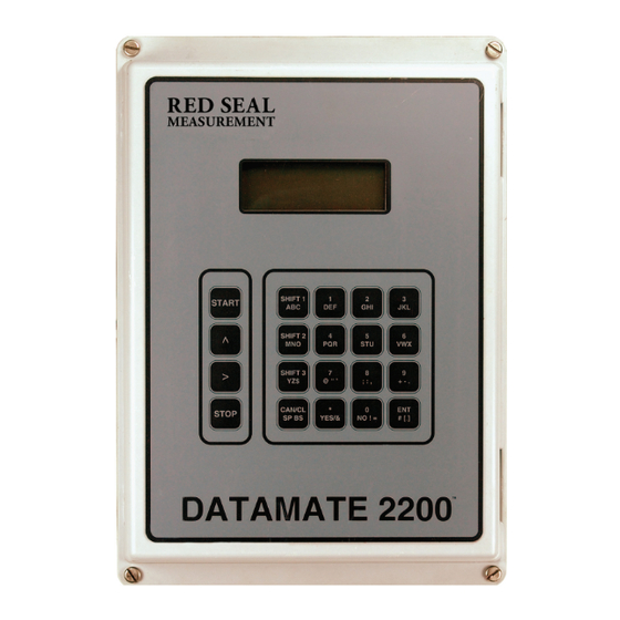
Page 8: Figure Locations 1.1 Lcd Display Unit Component Highlights
Datamate 2200 O&M KEYPAD LIQUID CRYSTAL DISPLAY ELECTRONICS ENCLOSURE HOUSING CONDUIT ENTRY FIGURE 1.1 LCD DISPLAY UNIT (WITH KEYPAD) COMPONENT HIGHLIGHTS Figure 1.1: LCD Display Unit Component Highlights (with keypad) Page 2... -
Page 9: Blind Unit Component Highlights
Datamate 2200 O&M ELECTRONICS ENCLOSURE HOUSING CONDUIT ENTRY Figure 1.2: Blind Unit Component Highlights FIGURE 1.2 - BLIND UNIT COMPONENT HIGHLIGHTS Page 3... -
Page 10: Lcd Display Unit (Less Keys) Component Highlights
Datamate 2200 O&M LIQUID CRYSTAL DISPLAY ELECTRONICS ENCLOSURE HOUSING CONDUIT ENTRY Figure 1.3: LCD Display Unit (Less Keys) Component Highlights FIGURE 1.3 LCD DISPLAY UNIT (LESS KEYS) COMPONENT HIGHLIGHTS Page 4... -
Page 11: Section 2: Read This First
CAUSE AN EXPLOSION. INSTALL THE Datamate 2200 IN AN AREA COMPATIBLE WITH THE HAZARDOUS ENVIRONMENT SPECIFIED ON THE APPROVALS TAG. The Datamate 2200 has been tested by an independent third party laboratory and has been found to meet the following standards:... -
Page 12: Section 3: Transmitter Installation
• maximum length of cable between the transmitter and the transducer must not exceed 1000 feet (300 meters) • mount the transmitter to a stable surface or instrument pole that will minimize vibration NOTE: Datamate 2200 transmitter requires 18 inches (450 mm) of clearance for opening the cover. WARNING: •... -
Page 13: Mounting To A Wall
Datamate 2200 O&M Mounting to a Wall Refer to Figure 3.2.1 to mount the Datamate 2200 transmitter to a wall or other flat rigid surface: • Use four 1/4-inch or M6 bolts and nuts to mount the transmitter to a wall or other flat surface. -
Page 14: Dimensional Data
Datamate 2200 O&M Dimensions are inches 8.50 6.00 6.00 12.00 10.75 10.75 5/16 DIA. HOLES MOUNTING DIMENSIONS 4 PLACES 6.88 Figure 3.2.1: Dimensional and Mounting Information Page 8... -
Page 15: Guidelines For Conduit
1. Attach the transducer cable connector to the threaded male connector on the transducer. 2. Bring the other end of the transducer cable into the Datamate 2200 through the top right conduit opening. Strip the cable cover back a minimum of 10” and a maximum of 12”. -
Page 16: Transducer Cable Connections
Datamate 2200 O&M TRANSDUCER CABLE MUST COME THRU THIS OPENING SEE DETAIL "A" CAPACITOR ASSEMBLY ATTACHED TO GROUND SCREW. REFERENCE DETAIL C. TRANSDUCER I/O INTRINSICALLY SAFE OUTPUTS DETAIL A GROUNDS CONNECT J2-2 AND J2-3 SHIELD TO THE DESIGNATED INTRINSIC SAFETY GROUND. -
Page 17: Transmitter Terminals
Datamate 2200 O&M START BATCH PB IN PB RETURN STOP BATCH PB IN HART OUT HART IN 12V RETURN (-) RS485 A RS485 B ALARM1 OUT ALARM RETURN ALARM2 OUT CURRENT1 OUT (+) CURRENT1 RETURN (-) CURRENT2 OUT (+) CURRENT2 RETURN... - Page 18 Datamate 2200 O&M Page 12...
-
Page 19: Section 4: Power Supply Wiring
Datamate 2200 O&M SECTION 4: POWER SUPPLY WIRING Wiring Guidelines WARNING: IMPROPER INSTALLATION IN A HAZARDOUS AREA COULD CAUSE AN EXPLOSION. For intrinsically safe installations: • Do not wire the transmitter until all electrical power to the transmitter has been shut off •... -
Page 20: Power Supply Wiring Connections
• Match power supply voltage with the correct terminals (Refer to Figure 4.3.1) • Shut off power before wiring transmitter The Datamate 2200 transmitter has 12 to 36 VDC, 115/230 VAC ± 10%, 20-40 VA power inputs. Figure 4.3.1 shows the power supply wiring terminals in the transmitter housing. -
Page 21: Power Supply Wiring Location And Connections
Datamate 2200 O&M TRANSDUCER CABLE ENTRANCE TRANSDUCER CABLE ENTRANCE DC POWER SUPPLY 12-36 VDC (-) 12-36 VDC (+) FIELD GROUND POWER CONNECTION GROUND NOTE: WIRE FIELD GROUND WIRE TO BE TERMINATED ON G CONNECTION JUMPER WIRE TO BE CONNECTED FROM GROU... - Page 22 Datamate 2200 O&M DETAIL "A" PROCESS CONTROL I/O HEADER FOR LCD DISPLAY START BATCH PB IN CONNECTOR PB RETURN STOP BATCH PB IN DESIGNATED ENTRIES SEE DETAIL A FOR I/O CABLES HART OUT HART IN 12V RETURN (-) RS485 A...
- Page 23 MODEL M CORIOLIS MASS PRIETARY TO ACTARIS AND PRIETARY TO ACTARIS AND SURFACE FINISH SURFACE FINISH FLOWMETER WITH DATAMATE 2200 FOR NONHAZARDOUS AREA FLOWMETER WITH DATAMATE 2200 FOR NONHAZARDOUS AREA .125 .125 SHALL NOT BE DUPLICATED, DISCLOSED, SHALL NOT BE DUPLICATED, DISCLOSED,...
- Page 24 Datamate 2200 O&M Page 18...
- Page 25 Datamate 2200 O&M Page 19...
-
Page 26: Section 5: Input/Output Wiring
SECTION 5: INPUT/OUTPUT WIRING General Guidelines The Datamate 2200 provides up to three (3) 4-20mA outputs (with HART option), and one (1) quadrature pulse output. (Refer to Figure 3.5.2 for Input/Output Cable Connections.) CAUTION: NEVER install or remove any board with the Datamate 2200 transmitter power on. -
Page 27: Pulse Output
Datamate 2200 O&M Pulse Output The totalizer pulse output is a two channel quadrature pulse from open-collector NPN transistors. Galvanically isolated to 2.5Kv, opto-coupler with 100 ohm ON resistance. Maximum Voltage 26.5 VDC. Maximum Current 10mA. At maximum flow, the output has a range up to 10,000 Hertz, which can represent any variable. -
Page 28: Alarm Output
The SSRs function as switches to make or break power to the alarm devices. The SSR outputs are not connected to a voltage source internally in the Datamate 2200. Figure 5.4.1 shows the connections for alarm devices that sense an open or closed contact. -
Page 29: Flow Direction Output
LCD also shows the direction of flow in the reverse direction by showing negative flow rates when the flow direction is programmed to forward. The 4-20mA output signal from the Datamate 2200 permits the user to configure the output to represent positive or negative measurement ranges. -
Page 30: Wiring Connections
Modbus . Modbus allows a computer or a handheld communicator to ® communicate directly with up to 248 Datamate 2200 transmitters and send commands necessary to configure: batching, alarms, outputs, etc., and to read all measured variables. -
Page 31: Rs485/Rs232 Converter Connections
Datamate 2200 O&M RS485/RS232 Converter Connections TD (A) Black TD (B) RD (A) RD (B) 1 RS485/RS232 Converter Serial Cable to PC 3 Twisted Pair to Datamate 2200 Power Supply/Transformer for Converter Figure 5.7.1: RS485/RS232 Converter Connections Page 25... -
Page 32: Hart ® (Option Card) Wiring Connections
Connect the ® 4-20mA outputs from each transmitter together so they terminate at a common load resistor, installed in series, with approximately 250 ohms impedance. Figure 5.9.1 illustrates the handheld communicator connections for configuring the Datamate 2200 via HART. DATAMATE DATAMATE... -
Page 33: Hart ® Communicator Connections
Datamate 2200 O&M Hart Communicator Connections ® DATAMATE Figure 5.9.1: HART Communicator Connections ® Page 27... -
Page 34: Section 6: Batch Wiring
The internal SSR outputs are not connected to a voltage source in the standard Datamate 2200. If the Datamate 2200 is purchased with the optional pilot SSRs, this connection is done at the factory;... -
Page 35: Relay Locations
Datamate 2200 O&M Electronics Module Optional Pilot Relays Figure 6.2.1: Relay Locations Figure - 6.2.1 - Relay locations FIELD CONNECTIONS DATAMATE 2200 HF BATCH CONTROL DEVICE 0-210V AC/DC 100 mA max. LF BATCH CONTROL DEVICE INTERNAL SOLID STATE RELAYS Figure 6.2.2.: Field Connections for Batch Devices That Do Not Require Pilot Relays FIGURE 6.2.2 FIELD CONNECTIONS FOR BATCH DEVICES THAT DO NOT REQUIRE PILOT RELAYS... -
Page 36: Field Connections For Batch Devices That Require Pilot Relays
Datamate 2200 O&M FIELD CONNECTIONS DATAMATE 2200 HF BATCH PILOT CONTROL DEVICE RELAY 12 VDC OPTIONAL BATCH CONTROL POWER SUPPLIED DEVICE SUPPLY FROM PILOT RELAYS VOLTAGE ELECTRONIC MODULE LF BATCH CONTROL PILOT DEVICE RELAY SOLID STATE RELAYS (PART OF ELECTRONIC MODULE) Figure 6.2.3.: Field Connections for Batch Devices That Require Pilot Relays... -
Page 37: Section 7: Startup
NOTE: All Datamate 2200 transmitters in the blind configuration are pre-programmed from the factory with ID number “247.” Any change to the Unit ID or protocol, power to the Datamate 2200 is to be recycled for the change to be acknowledged. The default password for NexLink: User ID: admin,... -
Page 38: Optional Lcd
Datamate 2200 O&M Optional LCD The Datamate 2200 transmitter is available with an optional LCD, as shown in Figure 7.3.1. The 4 x 20 digit four line display indicates all process measurements and any alarm warnings. • For information about using the LCD during flow meter zeroing, see Section 7.4. -
Page 39: Flow Meter Zeroing
LED will go off. The optional LCD will again indicate the flow rate. To abort at any time during the zeroing procedure, recycle power to the transmitter or press the CANCEL key on the Datamate 2200 enclosure if equipped. Ready for Process Measurement... -
Page 40: Ready For Batch Operation (Optional)
ELECTRICAL HAZARDS THAT CAN CAUSE PROPERTY DAMAGE, INJURY OR DEATH. The Datamate 2200 transmitter with optional keypad and LCD is a full featured two-stage batch controller. For accurate and repeatable batching, batch size should be large enough to allow the flow meter to run one (1) minute for each batch. If proper programming (Section 9) of the transmitter has been completed, the following procedures will allow you to control a batch with the Datamate 2200. -
Page 41: Starting A New Batch
Datamate 2200 O&M 7.6.6 Starting a New Batch After a batch has finished, the Datamate 2200 will display the amount of liquid delivered if a line of display has been set to BATCH TOTAL. If Run Mode Edit is Off, the pressing of the START button will start a new batch. If Run Mode Edit is On, press START twice to run the same size batch, or press START once, then enter the new batch size and press START again to run a batch of a different size. - Page 42 Datamate 2200 O&M 3. There are no phase changes (solids - liquids - gas) taking place in the process stream. This can be a particular problem when the process temperature changes because such changes can often induce precipitates or cause additional solid to dissolve.
-
Page 43: Api
Datamate 2200 O&M 7.9 API Datamate 2200 allows to measure density in degrees API. API gravity measures the relative density of liquid petroleum products, where 10°API is equivalent to the specific gravity of water. In order to provide these measurements, Datamate 2200 contains... -
Page 44: Actual/Standard Volume
Datamate 2200 O&M 7.10 Actual/Standard Volume The Datamate 2200 calculates actual gross volume and standard volume flow rates and totals. The actual volume is obtained directly dividing the measured mass by the measured density. Whereas the standard volume is the equivalent volume at a standard condition, obtained dividing the measured mass by density of the fluid under the standard conditions (Standard Density). -
Page 45: Net Oil And Well Testing (Optional)
To use the Net Oil functions, the user will have to set up the Well Data and Shrinkage Factor. Datamate 2200 can store data for up to 30 Wells, saving for each one of these the density of dry crude oil and density of produced water at the selectable reference temperature of 60°F or 15°C. - Page 46 Datamate 2200 O&M While running the well test, Datamate 2200 will provide the following real time measurement: • Elapsed test time. • Net Oil Rate, instant and average value during the elapsed time of the test. • Net Oil Total during the elapsed time of the test.
-
Page 47: Section 8: Troubleshooting
SECTION 8: TROUBLESHOOTING Customer Service NOTE: Make sure you have the model number and serial number of the transmitter and the transducer prior to contacting your Red Seal Measurement Representative. For local Customer Service assistance, contact your local RSM Representative or Distributor. -
Page 48: General Guidelines
WARNING: DO NOT REMOVE THE COVER OF THE DATAMATE 2200 TRANSMITTER TO TROUBLESHOOT THE UNIT IN A HAZARDOUS ENVIRONMENT. Troubleshooting a Datamate 2200 transmitter is performed in the following two parts: 1. Tests of wiring circuit integrity 2. Observation of the transmitters diagnostic tools, which includes the diagnostic software and LCD, digital diagnostic messages, and fault output levels. -
Page 49: Transmitter Diagnostic Messages
Datamate 2200 O&M Transmitter Diagnostic Messages The Datamate 2200 transmitter provides a large number of diagnostic messages, which can be viewed on the optional LCD display or in the NexLink software program. Alarms DSP Failure Alarm • The Datamate 2200 digital signal processor has temporarily lost communication... -
Page 50: Power Supply
Datamate 2200 O&M Power Supply Check for specified power at the transmitter’s terminals. If the transmitter has a nominal: • 115 VAC, 50/60 Hz power source board, the line terminal is labeled ‘7’ and the neutral terminal is labeled ‘4’. Place jumper on terminal on ‘4’ & ‘5’ and ‘6’ & ‘7’. -
Page 51: Transducer Resistances Nominal Value
3. Use a digital multimeter (DMM) to measure resistance and voltage between wire pairs, as indicated in Table 8.6.2. 4. Use Table 8.6.3 to verify correct wiring at the Datamate 2200 transmitter terminals. 5. If the transmitter is remotely mounted from the transducer, repeat the measurements at the transducer cable connector on the transducer to distinguish cable failure from transducer failure. -
Page 52: Transducer Tube Drive Test
Datamate 2200 O&M 8.6.1 Transducer Tube Drive Test The Datamate 2200 Coriolis Flow Transmitter incorporates a digital multimeter to provide diagnostic information on the transducer. This display permits the user to view four (4) diagnostic measurements from the transducer. These measurements are 1. - Page 53 Datamate 2200 O&M Analog Fault - 4 Analog Fault - 2 Analog Fault - 1 DSP PLL Not Locked DSP Loss Event RTD Failure Slug Flow Alarm 4-20 Failure DSP Failure RTD Failure Temperature Density % Concentration Concentration Rate Standard Volume Rate...
-
Page 54: Slug Flow Inhibit
• transmitter pulse outputs will go to 0 Hz • transmitter 4-20mA outputs will go to 0mA If the Datamate 2200 fails as a result of a “Tube Not Vibrating” or “Sensor Error,” the following will occur: • transmitter pulse outputs will go to the fallback value •... -
Page 55: Section 9: Programming With Optional Lcd
Navigation To configure the Datamate 2200 the user must navigate to the desired parameter (menu item) and then enter the required data. The menu tree is laid out in rows and columns. Navigation through the menus is accomplished as follows: The ENT key is pressed to enter the menu tree. -
Page 56: Main Menu
Datamate 2200 O&M MAIN MENU ---> (1) View Process Variables ---> 1. View Measurements ---> Mass Rate value (MRAT) Sect. 9.2 Sect. 9.2 Mass Total value (MTOT) Mass Total Forward value (MTOF) Mass Total Reverse value (MTOR) ---> Volume Rate value (VRAT) - Page 57 Datamate 2200 O&M MAIN MENU (continued) ---> (1) View Process Variables ---> 3. Well Test Data ---> Well# XX Testing Sect. 9.2 Sect. 9.2 Oil R: Oil A: Oil T: ---> Well# XX Testing Water R: Water A: Water T: --->...
- Page 58 Datamate 2200 O&M MAIN MENU (continued) ---> 4. Program ---> Enter Password ---> 1. Calibration ---> ---> 1. Zero menu (Sect. 9.4.1) Sect. 9.3 Sect. 9.4 2. Temperature (Sect. 9.4.2) 3. Density (Sect. 9.4.3) 4. Mass (Sect. 9.4.4) 5. Analog Ouputs (Sect. 9.4.5) 6.
-
Page 59: Main Menu (Operational Mode)
Datamate 2200 O&M Main Menu (Operational Mode) The main menu is the normal operational mode of the Datamate 2200 transmitter. In the main menu, all process measurements, outputs, alarms and error log can be viewed. In addition the error log can be cleared. Access to the Program mode is also available through the use of a password. - Page 60 Datamate 2200 O&M Menu or Display Description Main Menu This menu allows the user to review a list of parameters and diagnostics that 2. View Alarm Status are out of limits. The list is organized as last-in first-out. This will make the last event the first seen by the user.
-
Page 61: Well Testing
Well# XX Test Time [XX] Hours Datamate 2200 will display the well number selected, purge type and test duration. To start the test press ENTER or if you want to modify the selection made press CANCEL. Well# XX Purge XXXXXXXXXXXX... - Page 62 Dens:X.XXXX Elapsed: XX:XX:XX If the CANCEL key is pressed while running the test, Datamate 2200 will prompt if the user wants to stop the test. Pressing CANCEL will stop the test and the average net oil rate, net water rate and water cut as well as the net oil and the net water total will be saved in memory.
-
Page 63: Program Mode
Datamate 2200 O&M Program Mode The program mode for the Datamate 2200 transmitter provides access to the user based on the password level. A clear explanation of access to the program mode and the password levels is listed below. Menu or Display... - Page 64 Datamate 2200 O&M CALIBRATION MENU ---> Main Menu ---> Enter Password ---> Program 4. Program 1. Calibration ---> 1. Calibration ---> 1. Zero ---> Electronics Zero ---> 1. Elec Zero Params ---> Electronics Zero Sect. 9.5 Sect. 9.5.1 ---> StdDev --->...
- Page 65 Datamate 2200 O&M CALIBRATION MENU (continued) ---> Main Menu ---> Enter Password ---> Program 4. Program 1. Calibration ---> 1. Calibration ---> 5. Analog Outputs ---> 1. Analog 1 ---> 1. Analog 1 Params ---> Gain Sect. 9.5 Sect. 9.5.5 --->...
-
Page 66: Calibration Menu
Section 9.6.6. 9.5.1. Zero Calibration NOTE: Correctly zeroing the mass flow meter is critical for accurate mass flow measurement. The Datamate 2200 transmitter allows the user to review and modify the electronic zero, transducer zero and the system zero. Automatic Zero Procedure - See Section 7.4. Manual Zero Procedure To complete a Manual Zero, use the following menu and description chart to perform the following: •... - Page 67 Datamate 2200 O&M Menu or Display Description Electronic Zero Displays the current electronic zero and the standard deviation for the last 1. Elec. Zero automatic zero. With the correct access (level 2) the user can modify the Params displayed ZERO value with the ^ and > keys.
- Page 68 Datamate 2200 O&M Menu or Display Description System Zero Displays the current system zero and the standard deviation for the zero. 2. Zero System ZERO: SX.XXXXeSXX DEG SDEV: X.XXXXeSXX DEG ENTER to Calibrate CANCEL to Exit Choices from this menu are ENTER to re-zero and CANCEL to exit.
-
Page 69: Temperature Calibration
Datamate 2200 O&M 9.5.2 Temperature Calibration The Datamate 2200 transmitter temperature measurement is factory calibrated. NOTE: The temperature calibration if changed will affect the density measurement. After re-calibrating the temperature, the density measurement will require calibration. To calibrate the temperature measurement, use the following menu and description chart to perform the following: 1. -
Page 70: Density Calibration
Prior to re-calibrating the density, the temperature calibration should be verified. See Section 9.5.2 for the temperature calibration procedure. The Datamate 2200 transmitter density calibration is factory calibrated. To calibrate the density measurement, use the following menu and description chart to perform the following: 1. Enter Calibrate Density. - Page 71 Datamate 2200 O&M Menu or Display Description Calibrate Density Allows the operator to re-calculate the density factors C1 and C2. 2. Calibrate Density Pressing ENTER Displays the current density: DENS: X.XXXX g/cc ENTER to Calibrate CANCEL to Exit Pressing ENTER brings up: Air Frequency [_XX.XXXX]...
-
Page 72: Mass Calibration
• Open the downstream valve (Dump Mode) or Press the Remote Start (Batch Mode) and run product fluid into the container for a minimum of 1 minute • Weigh the drum or tank and compare the reading to that of the Datamate 2200 transmitter LCD •... - Page 73 Datamate 2200 O&M Menu or Display Description Calibrate Mass The dump calibration mode is used when the Datamate 2200 is not going to control 2. Dump Calib the process flow with its batch control outputs. Pressing ENTER will display Mass the current scaler: Scaler: XX.XXXXeSXX...
-
Page 74: Analog Output Calibration
Press CANCEL to Exit when complete. Calibrate Analog 1. From this menu the Datamate 2200 will re-determine the calibration factors with Calibrate 1 Analog the assistance of the user. The user is required to measure and enter the output current when directed. -
Page 75: Diagnostics Menu
Datamate 2200 O&M DIAGNOSTICS MENU ---> Main Menu --->Enter Password ---> Program 4. Program 2. Diagnostics 2. Diagnostics ---> 1. Self Test ---> Task List <ok> Sect. 9.6 Sect. 9.6.1 ---> 2. Alarm Test ---> 1. Alarm 1 Test Sect. 9.6.2 --->... -
Page 76: Diagnostic Menu
Datamate 2200 O&M Diagnostic Menu 9.6.1 Self Test Using the DIAGNOSTIC MENU TREE enter the self test function. The diagnostic menu provides test menus for the following: 1. Self Test 2. Alarm Test 3. Batch Relay Test 4. Analog Test 5. -
Page 77: Alarm Test
Datamate 2200 O&M 9.6.2 Alarm Test Using the DIAGNOSTIC MENU TREE enter the Alarm Test. The following chart highlights the Alarm Test feature. Menu or Display Description Diagnostics The alarm test can be used to force the alarm outputs open and closed one 2. -
Page 78: Batch Relay Test
Datamate 2200 O&M 9.6.3 Batch Relay Test Using the DIAGNOSTIC MENU TREE enter the Batch Relay Test. The following chart highlights the Batch Relay Test. Menu or Display Description Diagnostics The batch relay test can be used to force the batch relay outputs open and 3. -
Page 79: Analog Test
Datamate 2200 O&M 9.6.4 Analog Test Using the DIAGNOSTIC MENU TREE enter the Analog Test. The following chart highlights the Analog Test. Menu or Display Description Diagnostics The analog output tests may be used to provide a test current for testing 4. -
Page 80: Pulse Test
Output Num Pulses XXXXXX] Enter the number of pulses that the Datamate 2200 is to send (between 0 and 65000) with the ^ and > keys. When 0 is entered, pulses will be transmitted continuously until the CANCEL key is pressed. Press ENTER twice to confirm. -
Page 81: Tube Drive Test
Datamate 2200 O&M 9.6.7 Tube Drive Test The tube drive test calculates the drive efficiency of the transducer and process. Using the DIAGNOSTIC MENU TREE enter the Tube Drive Test. The following chart highlights the Tube Drive Test. Menu or Display Description... -
Page 82: Buttons Test
Datamate 2200 O&M 9.6.8 Buttons Test The buttons test allows the user to confirm the operation of the START, STOP, ENTER, ^, >, CANCEL, and ZERO buttons. Using the DIAGNOSTIC MENU TREE enter the Buttons Test. The following chart highlights the Buttons Test. -
Page 83: Lcd Test
Datamate 2200 O&M 9.6.9 LCD Test Using the DIAGNOSTIC MENU TREE enter the LCD Test. The following chart highlights the LCD Test. Menu or Display Description Diagnostics Allows the user to test the display by alternately setting all pixel dark and light 9. - Page 84 Datamate 2200 O&M CONFIGURATION MENU ---> Main Menu ---> Enter Password ---> Program 4. Program 3. Configuration ---> 3. Configuration ---> 1. Batch ---> Parameter Sect. 9.7 Sect. 9.7.1 ---> Unit ---> Batch Cutoff Qty ---> Trickle Offset Pt ---> Low Alarm Offset --->...
- Page 85 Datamate 2200 O&M CONFIGURATION MENU - continued ---> Main Menu ---> Enter Password ---> Program 4. Program 3. Configuration ---> 3. Configuration ---> 4. Display ---> Line 1 Sect. 9.7 Sect. 9.7.4 ---> Line 2 ---> Line 3 ---> 5. Xmit Variables --->...
- Page 86 Datamate 2200 O&M CONFIGURATION MENU - continued ---> Main Menu ---> Enter Password ---> Program 4. Program 3. Configuration ---> 3. Configuration ---> 5. Xmit Variables ---> 1. Flow Variables ---> 6. Special Mass ---> Totalizer Factor Sect. 9.7 Sect. 9.7.4 --->...
- Page 87 Datamate 2200 O&M CONFIGURATION MENU - continued ---> Main Menu ---> Enter Password ---> Program 4. Program 3. Configuration ---> 3. Configuration ---> 6. Outputs ---> 2. Analog ---> Parameter Sect. 9.7 Sect. 9.7.6 ---> Lower Range ---> Upper Range --->...
- Page 88 Datamate 2200 O&M CONFIGURATION MENU - continued ---> Main Menu ---> Enter Password ---> Program 4. Program 3. Configuration ---> 3. Configuration ---> 8. Characterize Meter ---> 3. Temp Calib Param ---> RTD Offset Sect. 9.7 Sect. 9.7.8 ---> 4. Density Params --->...
-
Page 89: Configuration Menu
• Characterize Menu 9.7.1 Batch Setup Configuration The Datamate 2200 transmitter has the option of a two stage batch controller with remote start stop feature. In this menu the batch control is configured. Using the CONFIGURATION MENU TREE enter Batch Setup Menu. - Page 90 Hi Alarm Offset [ XXXX.XX] The System Response Time is a feature the allows the Datamate 2200 to anticipate when to stop a batch if there is a significant time delay between the signal to stop flow and flow stopping. The default value is 0.0 seconds for no delay. The maximum delay is 60 seconds.
-
Page 91: Device Information
Datamate 2200 O&M 9.7.2 Device Information All information concerning the identification of the transmitter, transducer, and software revision is located in this menu. Using the CONFIGURATION MENU TREE enter Device Information. The following chart highlights the Device Information. Menu or Display Description 2. - Page 92 Datamate 2200 O&M Menu or Display Description 2. Device Information Electronics Model Number 2. Configuration Elec Model Num (continued) [XXXXXXX] Electronics Serial Number Elec Model Num [ XXXXXXXXX] Final Assembly Number Descriptor [ XXXXXXXXXXX.XX] Wetted Materials of the transducer Wetted Materials...
-
Page 93: Alarm Setup Configuration
Datamate 2200 O&M 9.7.3 Alarm Setup Configuration The Datamate 2200 transmitter has two high and low external alarms. These alarms can be programmed to represent any variable and system alarm. Using the CONFIGURATION MENU TREE enter the Alarm setup configuration. The following chart highlights the Alarm Setup Configuration. -
Page 94: Display Setup Configuration
The following chart highlights the Display Setup Configuration. Menu or Display Description Configuration The Datamate 2200 will allow the user to program three variables as a default on 4. Display the optional LCD display. If you wish to configure the display, press ENTER. -
Page 95: Transmitter Variables Configuration
Datamate 2200 O&M 9.7.5 Transmitter Variables Configuration In this menu it is possible to set the Units, Fallback, Alarm Setpoints for each variable measured. Also the % Solids/Concentration, Brix or Baume table is entered here. Using the CONFIGURATION MENU TREE enter the Transmitter Variable Configuration. - Page 96 Datamate 2200 O&M Menu or Display Description Configure Flow Vars Press ENTER to configure Standard Volume Flow. 3. Standard Vol Flow Use the UP or ACROSS key to select unit. Unit [XXXX Use the UP or ACROSS key to set the fallback value in the event of a fault condition.
- Page 97 Description Configure Flow Vars Press ENTER to configure Net Oil Functions. This menu will be active only if Datamate 2200 5. Net Oil Flow was purchased with the Net Oil and Well Testing option. It is important to input first the Well Data, before attempting to configure the Net Oil functions (please refer to the Configure Xmit Vars, 5.
- Page 98 Enter the label that will describe the new volume or mass unit, using the UP or ACROSS key. Totalizer Text [XXXX] Configure Flow Vars The Datamate 2200 can be configured for forward or reverse flow. Press the UP or ACROSS 8. Flow Direction key to scroll the options and press ENTER to select Configure Flow Vars Exit the Configure Flow Variables Menu 9.
- Page 99 Datamate 2200 O&M Menu or Display Description Configure Xmit Vars Press ENTER to configure Density measurements. 3. Density Use the UP or ACROSS key to select engineering unit to display the measured variable. Unit [XXXX If API is selected an extra prompt will appear allowing to select the type of fluid measured.
- Page 100 Datamate 2200 O&M Menu or Display Description Use the UP or ACROSS key to adjust the response time of the measurement in seconds. Damp Factor [XXXXXXXXXXXX] Configure Xmit Vars Press ENTER to configure Concentration, Brix or Baume Tables. 4. Concent./Solids Use the UP or ACROSS key to select engineering unit to display Concentration.
- Page 101 Datamate 2200 O&M Menu or Display Description Configure Xmit Vars Press ENTER to enter the data for each Well. 5. Well Data It is important to input first the Well Data and then configure the Net Oil function, before attempting to run a Well Testing (please refer to the Configure Xmit Vars, 5.
-
Page 102: Analog/Pulse/Rs485 Output Configuration
Datamate 2200 O&M 9.7.6 Analog / Pulse / RS485 Output Configuration Using the CONFIGURATION MENU TREE to enter the analog / pulse or RS485 output configuration. The following chart highlights the configuration of the pulse / 4-20mA or RS485 outputs. Menu or Display Description Configuration Configuration of the analog, pulse and communication outputs is completed 6. - Page 103 The protocol to be used in communication with the Datamate 2200 can be selected with the UP or ACROSS key Protocol [XXXXXXXXXXXXXXXXXX] Configure Outputs If the optional card is installed in the Datamate 2200, it can be configured 6. Option Card Configure Outputs Exit the configure outputs menu 7. Exit...
-
Page 104: Totalizer Reset
Datamate 2200 O&M 9.7.7 Totalizer Reset Using the CONFIGURATION MENU TREE enter the Totalizer Reset function. The following chart highlights the resetting of the totalizer. Menu or Display Description Configuration When ENTER is pressed the UP OR ACROSS key can select all or the 7. -
Page 105: Characterize Meter Configuration
Sensor, Zero, Temp Calib Params, Density Params, Mass Params, and Analog Outputs. Calibrate Sensor With the Datamate 2200 you can enter the time in seconds before the transmitter 1. Sensor Error goes into a sensor error delay. Maximum time: 30 seconds. - Page 106 Datamate 2200 O&M Menu or Display Description Zero Displays the current transducer zero. The transducer zero is the zero offset 2. Transducer Zero contribution of the transducer and installation. The transducer zero is determined by subtracting the electronic zero from the system zero.
- Page 107 Mass Scalar [ SX.XXXXeSXX] Characterize Meter 6. Analog Outputs The Datamate 2200 allows the user to modify the three (3) 4-20mA output calibration by using the Gain for zero mA and the Offset for 20mA 1. Analog 1 Gain [ GX.XXXXeGXX] Offset [ OX.XXXXeOXX]...
- Page 108 Datamate 2200 O&M Menu or Display Description Zero Displays the current transducer zero. The transducer zero is the zero offset 2. Transducer Zero contribution of the transducer and installation. The transducer zero is determined by subtracting the electronic zero from the system zero.
-
Page 109: System Menu
Datamate 2200 O&M SYSTEM MENU ---> Main Menu ---> Enter Password ---> Program 4. Program 4. System ---> 4. System ---> 1. Set Date ---> Date MM/DD/YY Section 9.8 Sect. 9.8.1 ---> 2. Set Time ---> Time HH:MM:SS Sect. 9.8.2 --->... -
Page 110: System Menu
When ENTER is pressed the following will be displayed Set Date [mm/dd/yy] 2. Set Time Set Time permits the user to confirm or set the Datamate 2200 to the time of day. When ENTER is pressed the following will be displayed Set Time [hr/min/sec] 3. -
Page 111: Dbase File Management
4. Reboot System To reboot the system press ENTER. No programmed values will be lost The display will list the following options: To REBOOT the Datamate 2200 ENTER to Continue CANCEL to Exit To reset the software to factory defaults press ENTER 5. - Page 112 Datamate 2200 O&M Menu or Display Description 6. Download DSP To download DSP file press ENTER: File DSP Download File (Not available with user password access) [DIGITALPLL] 7. Download To download Application File press ENTER: ApplFile Download DSP File (Not available with user password access)
-
Page 113: Section 9A: Programming With Hand Held Communicator
MODBUS protocol. Integral Keypad The ENTER key sends the Datamate 2200 into the displayed menu, locks in data choices made with the ^ and > keys, and confirms the selections, unless otherwise noted. The CANCEL key sends the Datamate 2200 into the next higher menus level, unless otherwise noted. - Page 114 Datamate 2200 O&M Summary of HART Specific Programming Features and Functions Section 5.7 — HART (Option Card) Wiring Connections Up to 15 transmitters can be connected into a HART multi-drop network. Section 9.2 - Main Menu (Operational Mode) Default Display: The default display is not available on the HART communicator.
- Page 115 When the correct password is entered, the menu will return to the previous selections. Enter “Program” at this point and data may be edited. NOTE: If the Datamate 2200 has been put in write protect mode via the keypad or NexLink, even though a correct password has been entered, the configuration of the device will not be changed. If this...
- Page 116 Program / 2. Diagnostics / 1. Self Test The Self Test diagnostic reports the status of various software subsystems in the Datamate 2200. All items should be “EMBEDDED”. Program / 2. Diagnostics / 2. Alarm Test / 1. Alarm 1 Test Program / 2.
-
Page 117: Hart Hhc Online Menu
9A.1 HART HHC Online Menu The main menu is the normal operational mode of the Datamate 2200 transmitter. Unlike viewing the menus from the Datamate 2200 display, the available program features are arranged slightly different when using the Hand Held Configurator. - Page 118 After the correct password has been entered, this selection is used to access the configuration and programming menus. NOTE: If the Datamate 2200 has been put in write protect mode via the keypad or NexLink, even though a correct password has been entered, the configuration of the device will not be changed.
- Page 119 1. Mass Cal Params allows viewing and manual entry of the mass flow scaler. The scaler may also be directly modified. 1. Mass Cal Params 2. Perform Dump Cal is used when the Datamate 2200 is not 2. Perform Dump Cal controlling the flow with its batch control outputs.
- Page 120 6. Outputs allows the user to configure the analog, pulse and HART outputs. 7. Totalizers allows the user to reset the Datamate 2200 totalizers. 8. Char’ze Meter may be used to configure/modify the transmitter and transducer characterization.
-
Page 121: Section 10: Model Number Designation
2. For Canadian and Non-NTEP state applications only. 3. W & M requires extended temperature display. HART Accessories PART NUMBER DESCRIPTION C0000012 Model 275 HART Hand Held Communicator w/ 4MB Memory 99999-700 Installation of Datamate 2200 HART Device Description on customer supplied Hand Held Communicator Page 115... -
Page 122: Section 11: Transmitter Specifications
Start/Stop Inputs Independent Momentary Contact Red Seal Measurement Manufacturer Instrument Model Number DM2200 Red Seal Measurement pursues a policy of continuous development and product improvement. The specifications above may thereof be changed without notice. Page 116... -
Page 123: Section 12 Replacing A Datamate 2100 With A Datamate 2200
Datamate 2200 O&M SECTION 12: REPLACING A DM2100 WITH A DM2200 Due to parameter changes from the DM2100 to the DM2200, the following information should be entered into the DM2200 upon changing out. • Refer to Pg. 58 of the DM2200 O&M Manual for correct path to Electronic Zero, RTD Offset, Density Calibration Coefficients, and Scalar. -
Page 124: Section 13: Forms For Return Of Goods
POLICY It is the policy of Red Seal Measurement that no returned materials would be accepted from any end user without a Return Material Authorization (RMA) number clearly visible on the exterior of the shipping container. Returned materials using the RMA number constitutes an agreement to comply with this policy and procedure. - Page 125 SECTION E: Please List the Material Involved in Your Claim: (Ship Material Pre-Paid Only) PART NUMBER DESCRIPTION REPLACEMENT ORDER SECTION F: For Red Seal Measurement Use ONLY DATE: _____________________ Value of Material : $ _______________ Authorized by (Up to $2,500): ____________________________________________ Credit Returns $2,500 –...
-
Page 126: Warranties And Limitations Of Damages And Remedies
Datamate 2200 O&M Warranties and Limitations of Damages and Remedies Seller warrants that at the time of delivery, products delivered or services to be performed hereunder will conform to applicable drawings and specifications and will be free from defects of materials and workmanship for a period of eighteen (18) months from the date of delivery to Customer, or twelve (12) months from the date of installation of products or the completion of services by Seller, whichever occurs first. - Page 128 U.S.A./International 1310 Emerald Road Greenwood, SC 29646-9558 Tel.: Toll-Free (800) 833-3357 (864) 223-1212 Fax: (864) 223- 0341 © 2013 Red Seal Measurement 01/13 Specifications subject to change without prior notification.
Need help?
Do you have a question about the Datamate 2200 and is the answer not in the manual?
Questions and answers