Table of Contents
Advertisement
Quick Links
Advertisement
Table of Contents

Related Manuals for CPS FlexOM Gateway V2


Summary of Contents for CPS FlexOM Gateway V2
- Page 1 Quick Guide for FlexOM Gateway V2 2/23/2023 Revision 3...
-
Page 2: Table Of Contents
-- -- Option 2b: DIN Rail Flat Mounting (in External DAS Box) -- -- 4G Cellular Antenna Installation (FlexOM-4G V2 only) -- -- Daisy Chain Wiring Using the CPS Connect Pro App -- -- Check the Internet Connection -- -- Modbus Device Settings... -
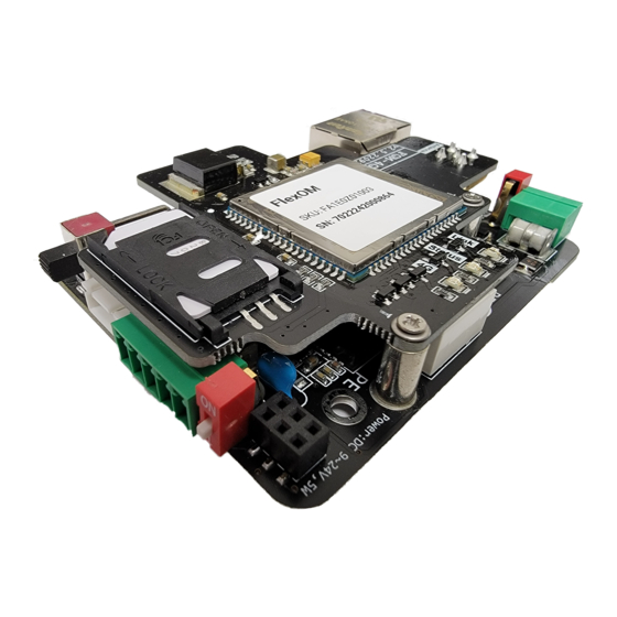
Page 3: Product Features
Product Features The FlexOM Gateway V2 is an IoT cloud-based gateway that allows the integration of various hardware and system scenarios Connect multiple CPS inverters and other devices to a single RS485 daisy chain RS485 pass-thru allows third-party controller to act as a client in parallel with the FlexOM... -
Page 4: Product Specifications
Product Specifications RS485 Interface No. of Ports 1 (A: 6-Pin Connector or B: 5-Pole Terminal Block) Protocol Modbus RTU Modbus RTU Mode Client Terminator for RS485 120 ohms Isolation 2.5 kV AUX Interface No. of Ports 1 (3-pole Terminal Block) Protocol Modbus RTU Modbus RTU Mode... - Page 5 Modbus TCP Mode Server Max. No. of Client Connections Cellular Interface (FlexOM-4G V2 product only) Cellular Standards LTE-FDD/LTE-TDD, WCDMA No. of SIM Slot Cellular Antenna Connectors 1 SMA female Bluetooth Interface Standard BLE 4.2 Antenna Built-in Power Parameters Input Voltage 9 to 24 Vdc Power Consumption 2.5 W, Max.
- Page 6 Physical Characteristics Housing Plastic IP Rating IP 20 Dimensions 70 mm / 100 mm / 28 mm (2.76 in x 3.94 in x 1.10 in) Weight 73g ( 0.16 lb ) Standards and Certifications (DoC) CE-EMC EN 55032 EN 55035 EN 61000-3-2 EN 61000-3-3 CE-RED...
-
Page 7: Dimensions And Interfaces
Dimensions and Interfaces 0.83 in 3.98 in (21 mm) (101 mm) 2.72 in (69 mm) Dimensions without DIN rail housing 1.26 in 4.06 in (32 mm) (103 mm) 3.03 in (77 mm) Dimensions with DIN rail housing Page 6... - Page 8 Dimensions and Interfaces 5-PIN Port B: External DAS box installation (see installation options 2a and 2b) Vin GND A+ B- G Caution: Caution: If the length of either the cable connecting to the RS485 port or the AUX port Before configuring the gateway, of the gateway is over 1000 meters, the switch for the 120 ohm terminating ensure the power switch is set to ON.
- Page 9 Confirm the gateway model by checking the model number and SN listed on the label on top of the gateway card. FlexOM Gateway V2 cards must have an Internet connection to enable remote data communications via the CPS Portal. The standard FlexOM Gateway V2 requires an Internet connection via the Ethernet port.
- Page 10 Dimensions and Interfaces Internet Interface: Ethernet (FlexOM Gateway V2) FlexOM Gateway V2 requires a connection to the Internet using Ethernet. Any LAN firewall ports must be opened before commissioning the FlexOM Gateway V2. The following ports must be opened both ways (for incoming and outgoing communications): TCP 1884 with destination IP 47.254.52.209...
-
Page 11: Led Indicators
LED Indicators APP Connect Indicates whether the CPS Connect Pro app is connected to the gateway and whether the device is being configured Light Off BLE Hardware Error Blink No Active Connection Light On Phone Connected RS485 Device Indicates whether the RS485 devices are connected to the gateway and whether... -
Page 12: Typical System Design And Diagrams
Pass-Through, and Figure 3: Multiple Devices Using One RS485 show the various options for connecting and managing data transmission from the RTU devices (inverters, weather instruments, etc.) to the CPS portal or an optional third-party data logger or SCADA. FlexOM Gateway V2... - Page 13 Typical System Design and Diagrams Modbus/TCP Pass-through FlexOM Gateway V2 can be used as a Modbus/TCP server when connected to a third-party SCADA system, and will forward various commands to the daisy chain. Inverters Model A Model A Model A...
- Page 14 9600 baud. This setting can be changed manually. Ensure all devices in the RS485 daisy chain are set to the same baud rate. Please check with CPS America regarding hardware compatibility prior to installation and commissioning. CPS Hotline (choose option #2): +1 855-584-7168...
-
Page 15: Safety Precautions
Safety Precautions NOTICE Before performing operations, read through this manual and follow all the precautions included to prevent accidents. The safety precautions provided in this document do not cover all possible safety precautions. shall not be liable for any consequence caused by the violation of the safety operation regulations and design, production, and usage standards. - Page 16 Safety Precautions Installation Ensure that the FlexOM Gateway V2 is not connected to a power supply and is not powered on before starting installation. Ensure that all electrical connections comply with local electrical standards. DANGER High voltage may cause electric shock and serious injuries during FlexOM Gateway V2 operation.
-
Page 17: Hardware Installation
Hardware Installation FlexOM Gateway V2 card can be installed one of two ways: Option 1: Attached internally to the existing communications board within the inverter wire-box Option 2: Mounted via DIN rail to an external DAS box In addition, a 4G cellular antenna must be installed in the... -
Page 18: Option 1: Internal Wire-Box Installation
FlexOM Gateway V2, a unique RS485 address for each inverter must be assigned using the HMI (LCD or CPS Connect Pro app). Refer to the specific CPS inverter User Manual for instructions on setting and assigning the RS485 Modbus address. - Page 19 Internal Wire-Box Installation 6-PIN Header After all standoffs have been inserted, install the FlexOM Gateway V2 by carefully aligning the 6-PIN Port A with the 6-PIN header in the upper left-hand corner of the communication board. Install the (3) screws removed in step 1...
- Page 20 FlexOM Gateway V2 as shown below). If applicable, connect the 3rd Party Datalogger to the AUX port in the bottom left-hand corner of the FlexOM Gateway V2 using the 3-PIN Connector provided in the accessories kit. A+ B- G RS485 3rd Party Data Logger...
- Page 21 6 below. To connect to the Internet via Ethernet, insert the RJ45 LAN cable into the Ethernet port of the FlexOM Gateway V2. The LAN connection must be able to access the Internet without port filtering behind the firewall (see note on page 9 regarding LAN firewall ports).
-
Page 22: Option 2A: Din Rail Side Mounting (In External Das Box)
Hardware Installation Option 2a: DIN Rail Side Mounting (in External DAS Box) FlexOM Gateway V2 card can also be installed inside an external DAS box and mounted with a DIN rail clip. Installation options 2a (side mounting) and 2b (flat mounting) on the following pages describe these steps. - Page 23 #1 Phillips screwdriver to fasten the two parts together with M3 screws. To ground the FlexOM Gateway V2 once installed in the DIN rail enclosure, clamp the ground wire into the screw at the position shown in the figure.
- Page 24 8 below. To connect to the Internet via Ethernet, insert the RJ45 LAN cable into the Ethernet port of the FlexOM Gateway V2. The LAN connection must be able to access the Internet without port filtering behind the firewall (see note on page 9 regarding LAN firewall ports).
-
Page 25: Option 2B: Din Rail Flat Mounting (In External Das Box)
Torque to 7 in-lbs using 3/16” socket hex driver. DIN Rail Clip M4 Flat Head Screw 12mm Standoffs To ground the FlexOM Gateway V2 once installed in the DIN rail enclosure, clamp the ground wire into the screw at the position shown in the figure. - Page 26 6 below. To connect to the Internet via Ethernet, insert the RJ45 LAN cable into the Ethernet port of the FlexOM Gateway V2. The LAN connection must be able to access the Internet without port filtering behind the firewall (see note on page 9 regarding LAN firewall ports).
-
Page 27: Cellular Antenna Installation (Flexom-4G V2 Only)
Hardware Installation 4G Cellular Antenna Installation (FlexOM-4G V2 only) Before closing the cover of inverter wire-box or external DAS box, check again that the gateway’s power switch is set to ON. POWER ON Screw one end of the antenna cable into the cable connector of the gateway (applicable to FlexOM-4G model only). -
Page 28: Daisy Chain Wiring
Daisy Chain Wiring (All FlexOM V2 Models and Configurations) FlexOM Gateway V2 uses a two-wire Modbus RS485 multipoint serial line system. Shielded, twisted pair, 22 AWG, stranded cable such as Belden 3106A is recommended for the daisy chain. Ensure that all devices in the daisy chain are properly connected according to each device’s 5-PIN or 3-PIN terminal block as shown in the diagram below. -
Page 29: Using The Cps Connect Pro App
Using the CPS Connect Pro App Scan the QR code with a mobile phone to complete the Connect Pro app download and installation. Or search for “CPS Connect Pro” in the Apple Store (iOS) or the Google Play Store (Android). - Page 30 NOTE: No WiFi dongle is required to interface or activate the FlexOM Gateway The Gateway will connect to the Internet via Ethernet or 4G, and the Gateway will connect to the CPS Connect Pro app via Bluetooth. Make sure your phone can Click "smart link" and the app...
- Page 31 During the process of connect- ing and entering the gateway configuration interface, the Connect Pro app will prompt detailed information in case of any abnormality. This feature SN barcode makes it easy for users to The BLE name includes the SN diagnose problems.
-
Page 32: Modbus Device Settings
Connecting the gateway to the Internet is the most important step. During the activation process, once the gateway is powered on it will attempt to connect to the Internet via 4G by default. If this attempt fails, it will automatically attempt to connect via Ethernet. - Page 33 Modbus Device Settings The gateway is configured with a default modbus ID range. Click "Scan Daisy Chain" and the gateway will scan the daisy chain. After scanning, a device list will appear with the default ID. The user can either rescan the target IDs individually in the list, or scan the daisy chain in...
-
Page 34: Reset / Restart
FlexOM-4G Gate- way V2 is installed and activated, it is recommended to contact the CPS Hotline to request confirmation that the gateway and attached RTU devices are populated in the CPS Monitoring Portal. CPS Hotline (choose option #2): +1 855-584-7168... -
Page 35: Cps Warranty Policy
2 years. For service, Chint Power Systems America will provide local support. For warranty terms, please refer to the CPS America accessories warranty policy in place at time of purchase. If your product requires troubleshooting or warranty service, contact your installer or dealer. If you... - Page 36 Service Hotline: 855-584-7168 CHINT POWER SYSTEMS AMERICA CO., LTD. Email: AmericaSales@chintpower.com Website: www.chintpowersystems.com Page 35...
Need help?
Do you have a question about the FlexOM Gateway V2 and is the answer not in the manual?
Questions and answers