Advertisement
Quick Links
Advertisement

Subscribe to Our Youtube Channel
Related Manuals for CPS G2


Summary of Contents for CPS G2
- Page 1 Quick Guide Flex Gateway G2 Revision 012219...
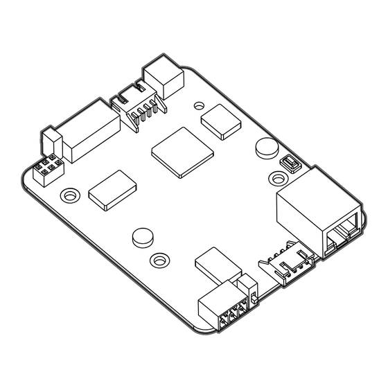
- Page 2 Interface & Indicators External Installation (Refer to Page 9-12) RS485 & DC in 9~24V Vin GND A+ B- G No-LCD INV Port Switch Signal Terminating Res Switch Reboot Button RS485 & DC in 9~24V Internal Installation (Refer to Pages 3-8) Ethernet Port WiFi Module Port Terminating Res Switch...
-
Page 3: Scope Of Delivery
OFF: Disconnected RS485 Blink: Device R/W OFF: No Activity Power Scope of Delivery Contents Model Note Flex Gateway G2 FG4E-US DC 9~24V WiFi Module CPLK-US Accessories D2XH Cable, 3 Standoffs with Screws, 3-Pin Connector, 5-Pin Connector FG4E Enclosure 80mm * 92.5mm * 35mm... - Page 4 Installation Option Internal in Wire-Box of the Inverter Example #1 Modbus/TCP Converter Weather Station Meter Ethernet Communication Box RS485 RS485 Fiber Data logger Switch Cellular Ethernet Ethernet RS485 AC/DC RS485 Power Surge Communication Box typically includes these devices. ID:101 ID:102 ID:117 Inverter Inverter...
- Page 5 Example #2 Communication Box Data logger Switch Cellular Ethernet Ethernet RS485 Meter RS485 AC/DC RS485 Power Surge Communication Box typically includes these devices. Weather Station RS485 Install the Flex Gateway in the first inverter of the RS485 ID:101 ID:102 ID:117 Daisy Chain.
- Page 6 Inverter Wire-Box The Communication Board within the Inverter Wire-Box Remove the (3) screws that attach the inverter Communication Board in the Wire-Box using a #2 Phillips bit. RS485 Port Replace the screws with the (3) standoffs included in the Flex Gateway Kit. 6-PIN Header Install the Flex Gateway by carefully aligning the 6-PIN header in...
- Page 7 Connect the 3rd Party Datalogger to the Pass-Through in the bottom left-hand corner of the Flex Gateway using the 3-Pin Connector provided in the Flex Gateway Kit. NOTE: Half duplex or "2-wire" RS-485 cabling must include a signal ground (or zero volt) reference for reliable operation.
- Page 8 WiFi Module WiFi module is connected to the WiFi port of the Flex Gateway via the D2XH cable. Scan the QR-code to complete the CPS Connect app download and installation by using mobile phones that can access the Internet. Page 7...
- Page 9 Inverter Wire-Box Ethernet Port Pass-through Inverter RS485 (A+ / B- / G) RS485 (A+ / B- / G) 3rd Party Data Logger Inverter:101 Inverter:117 Inverter:1 Inverter:17 PAD 1 PAD 2 The Flex Gateway may be installed in the middle of the inverter Daisy Chain. Or, alternatively the Flex Gateway may be used to combine two separate inverter Daisy Chains into one.
- Page 10 Installation Option External In Communication Box Screw M3*8 Screw M3*6 The Flex Gateway may be installed in the FG4E Enclosure as shown. The Flex Gateway Enclosure includes a DIN rail mounting clip for installation in an external NEMA4 communication box. Page 9...
- Page 11 Example #1 Modbus/TCP Converter Weather Station Meter Ethernet Communication Box RS485 RS485 Fiber Data logger Switch Cellular Ethernet Ethernet RS485 Pass-through RS485 (A+ / B- / G) 16AWG Ground Wire (not supplied) Typical Inverter (Vin / Gnd) RS485 (A+ / B- / G) AC/DC RS485 Power...
- Page 12 Example #2 Communication Box Data logger Switch Cellular Ethernet Ethernet RS485 Pass-through RS485 (A+ / B- / G) 16AWG Ground Wire (not supplied) Inverter (Vin / Gnd) RS485 (A+ / B- / G) AC/DC RS485 Power Surge ID:1 ID:2 ID:17 Inverter Inverter Inverter...
- Page 13 Example #3 Communication Box Data logger Switch Cellular Ethernet Ethernet RS485 Pass-through RS485 (A+ / B- / G) 16AWG Ground Wire (not supplied) RS485 AC/DC Inverter Surge Power (Vin / Gnd) RS485 (A+ / B- / G) Meter Weather Station RS485 RS485 With Meter &...
- Page 14 Open the firewall ports before commissioning ! If a firewall is used to protect the network, the following port must be opened both ways (incoming and outgoing communications): TCP 1883 with destination IP 47.254.52.209 If the Flex Gateway firmware version is lower than 1.6000, the following port must be opened both ways: TCP 80 and 88 with destination IP 47.254.31.163 If the user or site owner is unable to have those ports opened, he/she will not...
-
Page 15: Setup And Activation
WiFi Gateway Firmware “Password” WiFi Setting Next Open the CPS Connect app and click Select WiFi settings and connect to the “Flex Gateway” under the “Installer” tab. network name beginning with “CPLK-“. Ensure the D2XH Cable and WiFi Module are connected to the Flex Gateway card. - Page 16 Save the Config Once connected to the network, navigate “Inverter Baud Rate” : back to the CPS Connect app. NOTE: Do Speed 2400 / 4800 / 9600 / 14400 / 19200 not close the app as you will need to Parity E / N / O repeat the previ-ous steps.
- Page 17 Basic Ethernet RS485 Runtime: 22 Minutes Runtime: 25 Minutes MQTT Connection: DISCONNECT MQTT Connection: CONNECT MQTT Server Host: None MQTT Server Host: cps.j1st.io 1883 Routing: LINK_OFF Routing: LINK_ON MAC: 00005E113C08 MAC: 00005E113C08 IP Address: 0.0.0.0 IP Address: 192.168.1.100 Mask: 0.0.0.0 Mask: 255.255.255.0...
- Page 18 Back Advanced Settings Back Ethernet Execute Inverter Port DHCP Pass-through Port Protocol of Server Ethernet MQTT Reboot SunSpec Reset Upgrade Firmware When ”Reboot” is selected, this will only In the “Ethernet” settings, the user can restart the Flex Gateway. It will not erase connect the Flex Gateway to the two any settings.
- Page 19 Basic Ethernet RS485 --------------------------------------- Runtime: 25 Minutes Test: MQTT Connection: CONNECT 1. Server Connection [ OK ] MQTT Server Host: cps.j1st.io 1883 2. Query Inverter 1... Routing: LINK_ON MAC: 00005E113C08 IP Address: 192.168.1.100 Mask: 255.255.255.0 Gateway: 192.168.1.1 DNS: 6.6.6.6 DHCP...
- Page 20 Quit Email of Site Owner Next Press “Activate”. The app will prompt you Ensure the mobile phone is connected to for an internet connection. the Internet during this step. This will require the user to disable the Input the email address WiFi connection between his/hers smart "monitor@chint.com"...
- Page 21 Back Flex Gateway Site Name None Flex Gateway Name None Time Zone Apply Name a new site or choose an existing Click “Apply” to proceed with the activation. site. Name a new Flex Gateway. Choose the time zone of the site. Page 20...
- Page 22 Quit New Gateway Activate Basic Ethernet RS485 Flex Gateway Name: Genesis Model: FG4E-US SN: 1088000000106 Hardware Ver: V1.4.1751 Firmware Ver: V01.6142 DHCP Inverter Baud Rate 9600 N81 Modbus Range 1 ~ 16 Test Save the Config For verification purposes, please log out and close the app.
- Page 23 Service Hotline: 855-584-7168 CHINT POWER SYSTEMS AMERICA CO., LTD. Address: 1110 E Collins Blvd Richard- son Texas 75081 Email: AmericaSales@chintpower.com Website: www.chintpowersystems.com SHANGHAI CHINT POWER SYSTEMS CO., LTD. Headquarters: Building 4, No. 3255, Sixian Road, Songjiang District, Shanghai, China Tele: +86 -21 -3779 1222 -6300 Fax: +86 -21 -3779 1222 -6001...
Need help?
Do you have a question about the G2 and is the answer not in the manual?
Questions and answers