Table of Contents
Advertisement
Quick Links
MT-3 FM TransMiTTer
MainBoard
insTrucTion Manual
Covers Models:
VT-3H035-SXA300
VT-3H045-SXA300
© 1998–2010 Daniels Electronics Ltd. All rights reserved. No part of
this publication may be reproduced, stored in a retrieval system or
transmitted in any form or by any means, electronic, mechanical,
photocopying, recording or otherwise, without the prior written consent
of Daniels Electronics Ltd.
The stylized "Daniels Electronics Ltd." and "DE" logo are registered
Canadian and US trademarks of Daniels Electronics Ltd.
The stylized "Daniels Electronics Ltd." and "DE" logo are trademarks of
Daniels Electronics Ltd.
Document Number:
IM20-MT3TXMN
Daniels Electronics Ltd.
Revision:
5-0-0
Victoria, BC
Revision Date:
Feb 2010
PRINTED IN CANADA
Advertisement
Table of Contents

Related Manuals for Daniels Electronics MT-3

Summary of Contents for Daniels Electronics MT-3
- Page 1 Covers Models: VT-3H035-SXA300 VT-3H045-SXA300 © 1998–2010 Daniels Electronics Ltd. All rights reserved. No part of this publication may be reproduced, stored in a retrieval system or transmitted in any form or by any means, electronic, mechanical, photocopying, recording or otherwise, without the prior written consent of Daniels Electronics Ltd.
- Page 2 This document has been produced, verified and controlled in accordance with Daniels Electronics’ Quality Management System requirements. Please report any errors or problems to Daniels Electronics’ Customer Service Department. DOCUMENT REVISION Daniels Electronics Ltd. utilizes a three-level revision system. This DEFINITION system enables Daniels to identify the significance of a revision.
-
Page 3: Table Of Contents
Illustrations and Schematics ..........MT-3 FM Transmitter Block Diagram ............MT-3 FM Transmitter Mainboard Component Layout – Top..... MT-3 FM Transmitter Mainboard Component Layout – Bottom ....MT-3 FM Transmitter Mainboard Schematic Diagram ......Front Panel Board Component Layout Diagram ........ - Page 4 This Page Intentionally Left Blank MT-3 FM Transmitter Mainboard Instruction Manual IM20-MT3TXMN...
-
Page 5: General Information
Circuitry and jumpers on the transmitter mainboard control the operation of the modules as well as the overall operation of the MT-3 FM transmitter. Power and signal connections are made through the 48-pin Type F connector on the rear of the transmitter mainboard where they are then routed to the other MT-3 modules. - Page 6 This Page Intentionally Left Blank MT-3 FM Transmitter Mainboard Instruction Manual IM20-MT3TXMN...
-
Page 7: Vhf Low Band Performance Specifications
General Information mt-3 V H f l ow Ba n d Per f or m a n C e SPe C If I C atI o n S Parameter Specification Frequency Range: 29 to 38 MHz (VT-3H035-SWA300) 38 to 50 MHz (VT-3H045-SWA300) Carrier Frequency Stability: ±... -
Page 8: Physical Specifications
Gold-plated module connectors Module Design: • Compact Eurostandard modular design • Plug-in modules mate with the Daniels standard MT-3 Repeater Subrack • Subracks / modules comply with IEEE 1101, DIN 41494 and IEC 297-3 (mechanical size / modular arrangement) External Connections: RF Connection –... -
Page 9: Theory Of Operation
When SW1 is in the NORM position, +9.5 VDC is supplied to the transmitter circuitry and the transmitter can be keyed from any of the several Push-To-Talk inputs. MT-3 FM Transmitter Mainboard Instruction Manual IM20-MT3TXMN... - Page 10 TOT located on the FM Audio pins B10 and Z10 continue to function as the Processor. The TOT’s output is ‘AND’ed with the normal PTT WTO input. MIC PTT NTO signal (U2c) and the PTT NTO signal (U2d). MT-3 FM Transmitter Mainboard Instruction Manual IM20-MT3TXMN...
- Page 11 Ptt output front Panel Board Pin B24 on the backplane connector is an open The Front Panel Board is attached to the MT-3 drain output (Q9), which is pulled low anytime FM Transmitter Mainboard and is used to mount the transmitter is keyed and the synthesizer is the front panel switch, diode and microphone locked.
- Page 12 Theory of Operation transmitter Standby modes The MT-3 series transmitters have eight different standby modes that trade off standby current consumption for start-up speed. Three jumpers are found on the transmitter mainboard: Continuously enables the +9.5 VDC switched supply. Selects the power source for the FM Audio Processor.
- Page 13 The configuration of the MIC IN (pin Z4) and MIC mode # Standby Current turn-on time OUT (pin B4) lines on the MT-3 FM Transmitter 14 ma 150 mS Mainboard are controlled by jumpers J16 21 ma 10 mS and J17 respectively.
- Page 14 Theory of Operation Amplifier Circuits The MT-3 series Amplifier has six connections that are cabled to the transmitter board: • +13.8 VDC • +9.5 VDC • Enable • Forward Power Sense • Reverse Power Sense • Ground The +13.8 VDC supply (JP1-3) is always on while the +9.5 VDC supply (JP1-2) is always switched by a PTT signal.
- Page 15 Theory of Operation time-out-timer Circuitry TABLE 1: Time-out Jumper Settings and Duration The MT-3 FM Transmitter also has an associated programmable push-to-talk J32 J31 J29 J28 J26 J27 Minutes (PTT) time-out-timer (TOT) circuitry on the 0.01 transmitter mainboard. The TOT circuitry 0.01...
-
Page 16: Fm Audio Processor
FM Audio Processor are routed to the synthesizer module. • Dual microphone and balanced audio compression circuits • On-board multi-configurable temperature compensation to correct for changes in transmitter deviation over temperature caused by changing characteristics of synthesizers and oscillators MT-3 FM Transmitter Mainboard Instruction Manual IM20-MT3TXMN... - Page 17 2 Port Adjust Polarity Select P2-2 Subtone JU13 Tx Audio Control P4-1 Tx Audio P4-4 Control JU28 Direct Modulation Offset Buffer JU30 JU27 P4-3 B0232 JU43 Offset Coupling Select Direct Modulation Input FIGURE 1 MT-3 FM Transmitter Mainboard Instruction Manual IM20-MT3TXMN...
- Page 18 • 1 kHz tone at -8 dBm gives pre-emphasis response ±60% rated system deviation • 1 kHz signal compression set at ±84% rated system deviation Subtone Input 1 100 Hz tone at -18 dBm gives ±500 Hz All Other Audio Inputs Disabled MT-3 FM Transmitter Mainboard Instruction Manual IM20-MT3TXMN...
- Page 19 Output (P4-2), are gated by audio switches U5 DIRECT MODULATION inputs on the J1 control and U6 respectively which are controlled by the connector of the MT-3 Motherboard will be used Transmit Audio Control Input (P4-4). The audio (B20 for TX A, and A20 for TX B).
- Page 20 (R2) can accommodate a -25 dBm taken when directly modulating the transmitter to 0 dBm input signal. The microphone input is with the auxiliary input because the MT-3 limited and filtered and is output at the standard transmitters use direct FM modulation and there modulation output port.
- Page 21 Depending on the application, the signal can be amplified, AC or DC coupled and output to the Modulation Output or the Low Frequency / Direct Modulation Output port. Please consult the factory for specific jumper settings for your application. MT-3 FM Transmitter Mainboard Instruction Manual IM20-MT3TXMN...
- Page 22 S UBTO NE 1 INP UT 11K8 l ow = dat a CO NTRO L LE V E L JU16 hi gh = w i deband sel ect B0313 Microphone and Balanced Input Circuitry FIGURE 3 MT-3 FM Transmitter Mainboard Instruction Manual IM20-MT3TXMN...
- Page 23 1 0 P O LE LO WP AS S FI LTE R +8.0V SWD JU22 JU24 LTC1569-6 100K Vout +8.0V SWD 3K48 TP10 TP14 1.0uF 150pF 2K00 Div/Clk 22K1 30K9 1.0uF B0314 Limiter and Splatter Filter FIGURE 4 MT-3 FM Transmitter Mainboard Instruction Manual IM20-MT3TXMN...
- Page 24 = dat a CO NTRO L LE V E L JU16 hi gh = w i deband sel ect l ow = nar r ow band sel ect B0315 Bypassing Compression FIGURE 5 MT-3 FM Transmitter Mainboard Instruction Manual IM20-MT3TXMN...
- Page 25 MC33174 TC4S66F Tx Audio Control 50K0 47uF TCXO DC JU37 LE V E L JU39 DCS, LTR ADJUS T LOW FREQUENCY / DIRECT 10nF MODULATION OUTPUT B0316 TX Audio Control Circuitry FIGURE 6 MT-3 FM Transmitter Mainboard Instruction Manual IM20-MT3TXMN...
- Page 26 This Page Intentionally Left Blank MT-3 FM Transmitter Mainboard Instruction Manual IM20-MT3TXMN...
-
Page 27: Transmitter Alignment
Ir n o te MT-3 FM Transmitter modules are mainly made up of surface mount devices which should not be removed or replaced using an ordinary soldering iron. Removal and replacement of surface mount components should be... -
Page 28: Recommended Test Equipment List
Before proceeding with the transmitter alignment, check that the appropriate jumpers are installed. See Standard Factory Settings and Jumper Configuration section. Transmitter alignment is simplified by using a MT-3 Subrack, SM-3 System Regulator and RF extender cable to provide transmitter power and signal interconnection. Alternatively, connect... -
Page 29: Standard Factory Settings And Jumper Configurations
The standard jumper configuration for the transmitter mainboard is normally employed for transmitter alignment. In a standard configuration, the only alignment required on the MT-3 FM Transmitter Mainboard for a synthesized transmitter is to set the frequency switches (FSW1, FSW2, FSW3 and FSW4) for the desired channel frequency. -
Page 30: Fm Transmitter Mainboard Interconnection Pin Definitions
Separate amplifier power sense outputs mt-3 f m t r a nS m Itt er m aIn Bo a r d I n t e rC o n n eC t I o n PI n d e f In It Ion S The MT-3 series transmitter employs a 48-pin Eurostandard connector for interfacing to all transmitter power, audio and control functions. -
Page 31: Fm Audio Processor Alignment
1.8 kHz tone @ +10 dBm. Once that level is set (R29), it is not adjusted again. The rest of the tuning instructions are carried out while the transmitter frequency is set for the channel, which is roughly in the middle of the band of pre-programmed channels. MT-3 FM Transmitter Mainboard Instruction Manual IM20-MT3TXMN... - Page 32 1 kHz Tone @ -8 dBm R31 (Balanced) Adjust and measure. ± 3 kHz Deviation Monitor 1 kHz Tone @ -18 dBm AF Gen Change level. R31 (Balanced) Measure and confirm. ± 1 kHz Tolerance on this measurement is ± 50 Hz MT-3 FM Transmitter Mainboard Instruction Manual IM20-MT3TXMN...
- Page 33 2.5 kHz in 100 Hz steps. exceed maximum deviation. Balanced Audio Input Apply tone. AF Gen 1 kHz @ -18 dBm Perform AF Frequency As per test sheet limits Response from 300 Hz to (FIT-018) 5 kHz. MT-3 FM Transmitter Mainboard Instruction Manual IM20-MT3TXMN...
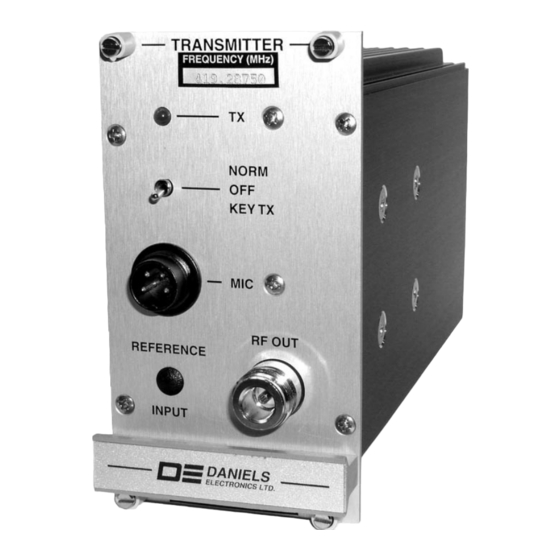
- Page 34 FRONT VIEW Adjust and measure. ± 3kHz Deviation Monitor DANIELS ELECTRONICS LTD TITLE: TX MICROPHONE CONNECTOR DETAILS DATE: 28 MARCH 2005 DRAWN BY: EVA DANIELS REV DATE: - - - DWG No: B0486-01 MT-3 FM Transmitter Mainboard Instruction Manual IM20-MT3TXMN...
-
Page 35: Troubleshooting
0.9 V P-P nB 0.2 V P-P nB *tP8 3.0 V P-P wB 1.8 V P-P wB 1.8 V P-P wB 0.4 V P-P wB *These values will differ depending on the oscillator / synthesizer model. MT-3 FM Transmitter Mainboard Instruction Manual IM20-MT3TXMN... -
Page 36: Temperature Compensation
I o Pr oC eS So r J u m Per C o n f I Gu r at Io n S For Default / CTCSS / LTR® / DCS configurations, see Table 3. MT-3 FM Transmitter Mainboard Instruction Manual IM20-MT3TXMN... - Page 37 Open Open for low band transmitter CTCSS and LTR® / DCS. Single Open Coupling Capacitor Selection Installed Installed Installed Single Coupling Capacitor Selection (Default) Installed Installed Installed 1 of 2 1 of 2 MT-3 FM Transmitter Mainboard Instruction Manual IM20-MT3TXMN...
- Page 38 This Page Intentionally Left Blank MT-3 FM Transmitter Mainboard Instruction Manual IM20-MT3TXMN...
-
Page 39: Illustrations And Schematics
P rI nt e d CI rC uI t Bo ard n umB e rI nG Co nV e nt I o n Daniels Electronics Ltd. has adopted a printed circuit board (PCB) numbering convention in which the last two digits of the circuit board number represent the circuit board version. -
Page 40: Fm Transmitter Block Diagram
+ 9.5 VDC SWITCHED TX STANDBY PTT OUTPUT PTT OUTPUT DANIELS ELECTRONICS LTD TITLE: MT-3 TRANSMITTER BLOCK DIAGRAM DATE: 25 JUN 03 DRAWN BY: S. EARTHY DWG No: B0286-04 REV DATE: 07 MAR 05 MT-3 FM Transmitter Mainboard Instruction Manual IM20-MT3TXMN... -
Page 41: Fm Transmitter Mainboard Component Layout - Top
LPF15 B R12 B T B7 B C5 R36 B C22 B TP26 T I7 LPF16 B TITLE: MT-3 TRANSMITTER MAIN BOARD (TOP) B C4 R13 B R37 B T B7 C23 T TP27 T J6 LPF17 B B E4... -
Page 42: Fm Transmitter Mainboard Component Layout - Bottom
COMPONENTS NOT INSTALLED 'Y' Position 'X' Position DANIELS 'Y' Position 'X' Position ELECTRONICS LTD AM/FM STANDBY MODES TITLE: MT-3 TRANSMITTER MAIN BOARD (BOTTOM) DESIG MODE 1 MODE 2 MODE 3 MODE 4 Not Installed Installed Installed Installed DATE: 9 OCTOBER 2001... -
Page 43: Fm Transmitter Mainboard Schematic Diagram
J30-D10 C10 J30-Z4 C5 J30-Z30 V3 LPF8 C10 LPF24 U7 F10 R16 Q8 R30 H9 R43 M11 TP17 L7 TP30 Q12 U2b G13 'Y' Position 'X' Position 'X' Position 'Y' Position 'X' Position MT-3 FM Transmitter Mainboard Instruction Manual IM20-MT3TXMN... -
Page 44: Front Panel Board Component Layout Diagram
MIC INPUT PF1-1 MIC-1 PF1-4 HIGHEST REFERENCE DESIGNATORS DANIELS ----- ELECTRONICS LTD VICTORIA BC. ----- ----- TITLE: MT-3 FRONT PANEL BOARD SCHEMATIC DIAGRAM UNUSED REFERENCE DESIGNATORS 07 APRIL 92 M. GAUBE DATE: DWN BY: APRVD: ----- ----- ----- 01-S-01-01 DWG No.:... -
Page 45: Fm Audio Processor Board Component Layout Diagram
C49 D2 JU24 E2 R24 C1 R49 G1 R74 I2 DATE: 19 JAN 2010 BOARD NO: 43-911923 C25 H1 C50 P3 JU25 B1 R25 D2 R50 B1 R75 C2 DWG No: 03-T-01-01 REV DATE: MT-3 FM Transmitter Mainboard Instruction Manual IM20-MT3TXMN... -
Page 46: Fm Audio Processor Board Schematic Diagram
DATE: 19 APR 2000 DWN BY: LARRY JOE JU30 JU40 DWG No: 03-S-05-01 DWG REV DATE: 19 Jan 2010 ----- ----- ----- ----- BOARD No: 43-911923 Rev. 2.3 REVISED BY: LARRY JOE ----- ----- MT-3 FM Transmitter Mainboard Instruction Manual IM20-MT3TXMN... -
Page 47: Parts List
PartS lISt mt-3 fm t r an Sm It t er m aI n B oa r d electrical Parts list – VT-3H035-SXA300 & VT-3H045-SXA300 Designator Description Part Number CONN1 CONNECTOR, F/48 MALE, R/A PCB 3720-6048M0RA CAP., SM, 10uF TANT., 10%, 35V 1055-6D106K35 CAP., SM, 1uF TANT., 20%, 35V... - Page 48 Parts List mt-3 fm transmitter mainboard electrical Parts (Continued) Designator Description Part Number DIODE, BAS16, SWITCHING, SOT23 2100-BAS16000 FSW1 SWITCH, BCD-16 STEPS,5 PIN,PCB 5273-16BCD001 FSW2 SWITCH, BCD-10 STEPS,5 PIN,PCB 5273-10BCD001 FSW3 SWITCH, BCD-10 STEPS,5 PIN,PCB 5273-10BCD001 FSW4 SWITCH, BCD-10 STEPS,5 PIN,PCB...
- Page 49 Parts List mt-3 fm transmitter mainboard electrical Parts (Continued) Designator Description Part Number RES., SM, 27K4 0805, 1%,100ppm 1150-4A2742FP RES., SM, 10K0 0805, 1%,100ppm 1150-4A1002FP RES., SM, 10K0 0805, 1%,100ppm 1150-4A1002FP RES., SM, 10K0 0805, 1%,100ppm 1150-4A1002FP RES., SM, 1K00 0805, 1%,100ppm 1150-3A1001FP RES., SM, 10K0 0805, 1%,100ppm...
- Page 50 Parts List mt-3 fm transmitter mainboard mechanical Parts list VT-3H035-SXA300 & VT-3H045-SXA300 Description Part Number Qty. CABLE, CONFORM., 31mm/5mm/4mm 7489-C1079100 CASE, 14HP RF PLUG-IN, MT-3 TX 3702-62502010 CONN., N JACK, PANEL MNT,C/SNK 5184-10923011 CONNECTOR, MIC., 4 PIN, MALE 5040-114ST0BK FASTENER, QUICK RELEASE, GRAY 3702-10000120 FERRITE, BEAD,43MIX,3x3.5mm OD...
-
Page 51: Front Panel Board
CAP, 10nF CER,0805,10%,50V,X7R 1008-4A103K5R CAP,100nF CER,0805,10%,50V,X7R 1008-5A104K5R CAP,330nF CER,0805,20%,25V,X7R 1008-5A334M3R CAP, 10nF CER,0805,10%,50V,X7R 1008-4A103K5R CAP., SM, 1uF TANT., 20%, 16V 1055-5A105M16 CAP, 10nF CER,0805,10%,50V,X7R 1008-4A103K5R CAP,330pF CER,0805,5%,100V,C0G 1008-2A331J1G CAP, 10nF CER,0805,10%,50V,X7R 1008-4A103K5R CAP,1uF C,1206,+80-20%,25V,X7R 1008-6B105Z3R MT-3 FM Transmitter Mainboard Instruction Manual IM20-MT3TXMN... - Page 52 1150-0A0R0000 POT.,SM/4mmSQ,5K0,MUL/TRN,SIDE 1174-DM2502J0 RES., SM, 100K 0805, 1%,100ppm 1150-5A1003FP RES., SM, 18K2 0805, 1%,100ppm 1150-4A1822FP RES., SM, 1M00 0805, 1%,100ppm 1150-6A1004FP RES., SM, 18K2 0805, 1%,100ppm 1150-4A1822FP RES., SM, 2K21 0805, 1%,100ppm 1150-3A2211FP MT-3 FM Transmitter Mainboard Instruction Manual IM20-MT3TXMN...
- Page 53 RES., SM, ZERO OHM JUMPER,0805 1150-0A0R0000 RES., SM, ZERO OHM JUMPER,0805 1150-0A0R0000 RES., SM, 20K0 0805, 1%,100ppm 1150-4A2002FP RES., SM, 18K2 0805, 1%,100ppm 1150-4A1822FP RES., SM, 18K2 0805, 1%,100ppm 1150-4A1822FP RES., SM, 15K4 0805, 1%,100ppm 1150-4A1542FP MT-3 FM Transmitter Mainboard Instruction Manual IM20-MT3TXMN...
- Page 54 RES., SM, 100R 0805, 1%,100ppm 1150-2A1000FP IC, SA571D, COMPANDOR, SO-16L 2327-SA571D00 IC, MC33174, QUAD OP AMP,SO-14 2304-33174N14 IC, MC33174, QUAD OP AMP,SO-14 2304-33174N14 IC, LTC1569I,LPF,10TH ORD,SO-8 2326-15696N08 IC, 4S66F,BILATERAL SWITCH,SMV 2375-4S66FSMV IC, 4S66F,BILATERAL SWITCH,SMV 2375-4S66FSMV MT-3 FM Transmitter Mainboard Instruction Manual IM20-MT3TXMN...
-
Page 55: Revision History
X installed for FM Products & Y installed for AM Products • Update Tx Front Panel Component Dwg: 43-921212-01-T-01-01 to 43-921212-01-T-02-01 • Update specification tables and part list Revision History continued next page MT-3 FM Transmitter Mainboard Instruction Manual IM20-MT3TXMN... - Page 56 Improve the Low Band transmitter’s standard subtone response. 6154 VHF and UHF Audio Processor Max Dev tuning change. 6344 Remove all references specific to the MT-3 800/900 MHz product. 6347 Discontinue the MT-3 UHF 400 and VHF 150 modules. •...
Need help?
Do you have a question about the MT-3 and is the answer not in the manual?
Questions and answers