Table of Contents
Advertisement
Quick Links
Advertisement
Table of Contents
Troubleshooting

Subscribe to Our Youtube Channel
Related Manuals for Furuno LH-5000


Summary of Contents for Furuno LH-5000
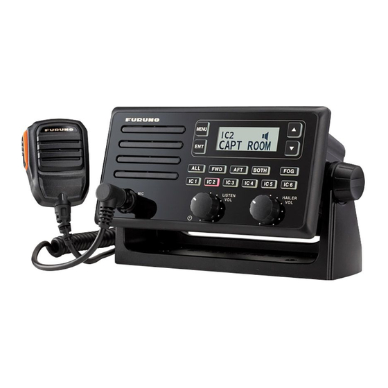
- Page 1 OPERATOR'S MANUAL LOUD HAILER LH-5000 Model www.furuno.com...
- Page 3 If the equipment is hot to the touch or is Loud Hailer emitting strange noises, turn off the power 0.45 m 0.30 m LH-5000 immediately and contact your dealer for Intercom Speaker advice. 2.25 m 1.50 m ISP-5000 Do not operate the equipment with wet hands.
-
Page 4: Table Of Contents
LH-5000 Operator’s Manual Contents Contents Foreword ....................1 System Configuration ................2 Equipment List ..................3 1. Installation ..................5 1.1 Installing the Loud Hailer ............... 5 1.2 Installing the Microphone ............... 8 1.3 Installing the Intercom Speaker (Optional) ........9 1.4 Installing the Extension Cable (Optional) ........ - Page 5 LH-5000 Operator’s Manual Contents 2.10 Hailing by Voice ................. 27 2.11 Sounding Warning Signals ............28 2.12 Transmitting the Auxiliary Signal ..........32 2.13 Setting the Alarm Mode ............. 33 2.14 Setting the Siren Mode .............. 35 2.15 Setting the Key Beep ..............36 2.16 Renaming the Intercom Station ..........
-
Page 6: Foreword
LH-5000 Operator’s Manual Foreword Foreword FURUNO LH-5000 loud hailer (LH-5000) is designed for a wide variety of ships, requiring high quality onboard communications under almost any circumstances. Features Hail, intercom, and alarm functions available Built-in high quality speaker Eight warning signals... -
Page 7: System Configuration
LH-5000 Operator’s Manual System Configuration System Configuration... -
Page 8: Equipment List
LH-5000 Operator’s Manual Equipment List Equipment List Standard Supply: Part Name Type Remarks Loud Hailer LH-5000 Main body Microphone MIC-5000 Hanger Accessories Hanger Knob Microphone Hanger Cushion Template See packing list for details Tapping Screw Installation Materials (ST4.0 x 16) Tapping Screw (PA4.0 x 25) - Page 9 LH-5000 Operator’s Manual Equipment List Optional Supply: Part Name Type Outline Remarks Intercom Speaker ISP-5000 Max.6 (with Hanger) packing Option list for Extension Cable EX-CBL-LH details for microphone...
-
Page 10: Installation
1. Installation Installing the Loud Hailer For desktop mounting Step 1 Put the hanger in a location where it is easy to install the LH-5000 Loud Hailer. Step 2 Fix the hanger with four screws. Step 3 Set the loud hailer to the hanger. - Page 11 LH-5000 Operator’s Manual Installation Signal Cable Power Cord Hanger Loud hailer Tapping screw(PA4.0 x 25) Hanger knob For flush mounting Step 1 Determine the position of installation holes according to the marking template and drill the hole. Step 2 Pry off the frame from the front panel.
- Page 12 LH-5000 Operator’s Manual Installation Make sure that every signal cable is firmly connected. Step 5 Place the LH-5000 Loud Hailer in the hole and fix it with four screws. Step 6 Attach the microphone to the front microphone connector on the loud hailer.
-
Page 13: Installing The Microphone
LH-5000 Operator’s Manual Installation Note Tape the unused cables to prevent short. Installing the Microphone Step 1 Determine a location where it is easy to install hanger. Step 2 Fix the hanger with three screws. Step 3 Place the microphone into the hanger. -
Page 14: Installing The Intercom Speaker (Optional)
LH-5000 Operator’s Manual Installation Installing the Intercom Speaker (Optional) For desktop mounting Step 1 Put the hanger in a location where it is easy to install the intercom speaker. Step 2 Fix the hanger with four screws. Step 3 Set the intercom speaker to the hanger. - Page 15 LH-5000 Operator’s Manual Installation For flush mounting Step 1 Determine the position of installation holes according to the marking template and drill the hole. Step 2 Pry off the frame from the front panel. Step 3 Paste the cushion on the back of the front panel by the double-side tape on the cushion.
-
Page 16: Installing The Extension Cable (Optional)
LH-5000 Operator’s Manual Installation Panel Signal cable Template 4 Frame Cushion 5 Intercom speaker Tapping screw (PA4.0 x 25) Installing the Extension Cable (Optional) For thru-wall mounting Step 1 Drill a round or square hole on the ship panel. The diameter of the hole ranges from 20 mm to 25 mm. - Page 17 LH-5000 Operator’s Manual Installation Step 2 Thread the extension cable through the hole. Step 3 Place the seal, cable holder, and waterproof cover sequentially around the extension cable. Step 4 Fasten the nut. Step 5 Fasten the three screws. Step 6 Put the cover on the extension cable and tighten it.
-
Page 18: Connecting The Cable
LH-5000 Operator’s Manual Installation Connecting the Cable The following diagram illustrates how to connect the cable. 1.5.1 Understanding the Cable Before you connect the cable, it is recommended to know the corresponding relationship about cables. For pig-tail cable-1... - Page 19 LH-5000 Operator’s Manual Installation Wire color Function Remark PURPLE FWD+ Forward horn (+) output GRAY FWD- Forward horn (-) output BROWN Chassis GND Forward horn chassis GND PURPLE AFT+ AFT horn (+) output GRAY AFT- AFT horn (-) output BROWN...
-
Page 20: Connecting The Pig-Tail Cable And Power Cord
LH-5000 Operator’s Manual Installation Wire color Function Remark PURPLE SPK+ Intercom speaker (+) output GRAY SPK- Intercom speaker (-) output BROWN Chassis GND Intercom speaker chassis GND GREEN CALL Call signal input WHITE Call signal GND For power cord-1 to 2... - Page 21 LH-5000 Operator’s Manual Installation Step 2 Referring to the figure below, place heat shrink tubes on the wires, and then solder the correction point. Step 3 Move the heat shrink tubes to the soldered correction, and then apply heat to the tubes.
-
Page 22: Connecting The Microphone And Extension Cable
LH-5000 Operator’s Manual Installation 1.5.3 Connecting the Microphone and Extension Cable Step 1 Remove the protective cover of the rear microphone connector. Step 2 Connect one end of the extension cable to the connector on the unit and tighten it. -
Page 23: Connecting The Ground Cable
LH-5000 Operator’s Manual Installation Step 3 Secure the other end of the extension cable to the panel. Step 4 Connect the microphone to the connector of extension cable. 1.5.4 Connecting the Ground Cable Step 1 Loosen the screw on the rear back of the unit. - Page 24 LH-5000 Operator’s Manual Installation Step 2 Place the grounding wire on the screw. Step 3 Tighten the screw again.
-
Page 25: Operation Overview
LH-5000 Operator’s Manual Operation Overview 2. Operation Overview Product Controls Front Panel 15 14 Part Name Part Name Front Microphone Connector Down Key Speaker Up Key ALL Key Both Key Intercom Selector Keys (IC1-IC6) Listen Volume Control/Power On-Off Forward Key... -
Page 26: Turning The Power On/Off
External Speaker/Alarm/AUX (IC1–IC6) Signal Cable Hailer Speaker Cable Rear Microphone Connector Turning the Power On/Off To turn on the LH-5000, rotate the Listen Volume Control/Power On-Off knob clockwise. To turn off the LH-5000, rotate the Listen Volume Control/Power On-Off knob counterclockwise. -
Page 27: Adjusting Key Backlight
Step 3 Press Up or Down key to increase or decrease the brightness of the keys on the front panel. Step 4 Press ENT key to confirm your settings. If you do not adjust the brightness within 60 seconds, the LH-5000 returns to the previous mode automatically. Adjusting the Contrast Step 1 Press the MENU key on the front panel. -
Page 28: Calling All Speakers
LH-5000 Operator’s Manual Operation Overview Volume Control knob. To adjust the volume from the intercom or horn speaker, rotate the Hailer Volume Control key. Calling All Speakers All speakers include all the six intercom speakers and both horn speakers. Step 1 Press the ALL key on the front panel. -
Page 29: Calling A Specific Intercom Speaker
LH-5000 Operator’s Manual Operation Overview All the keys from IC1 to IC6 light red and the following information appears on the screen. Step 2 Press and hold the PTT key on the microphone and speak into the microphone. The following information appears on the screen. -
Page 30: Receiving A Call From An Intercom Speaker
LH-5000 Operator’s Manual Operation Overview Note The intercom speaker name appears in the bottom line of LCD. To rename the name, see 2.16 Renaming the Intercom Station. Step 2 Press and hold the PTT key on the microphone and speak into the microphone. - Page 31 For example, the LH-5000 receives calls from IC1 and IC 5 at the same time, it will handle the call from IC1 first and then the call from IC 5.
-
Page 32: Hailing By Voice
LH-5000 Operator’s Manual Operation Overview Step 4 After completing your conversation, press the ALL key to return to the home screen, or press the same selected key (IC1-IC6) to back to previous mode. Manually receiving a call from a single station Step 1 Press the selected key (IC1–IC6) and hold the PTT key on... -
Page 33: Sounding Warning Signals
After speaking, press the ALL key to return to the home screen. 2.11 Sounding Warning Signals The LH-5000 has eight warning signals including manual, yelp, underway, stopped, sailboat, towed, anchored, and aground. The manual and yelp signals are sounded when you press and hold the PTT key on the microphone. However, the remaining warning signals are given when you press ENT key on the front panel. - Page 34 LH-5000 Operator’s Manual Operation Overview Warning Function Remarks Signal For power- One 5-second blast at 120-second interval. driven vessels Underway underway. 120s Underway Signal For power- Two 3-second blasts, with a 2-second driven vessel interval between each blast, repeated every that is 120 seconds.
- Page 35 LH-5000 Operator’s Manual Operation Overview Warning Function Remarks Signal For vessels One 3-second blast, followed by one 2- under tow. second interval, one 1-second blast, one 2- second interval, one 1-second blast, one 2- second interval, and one 1-second blast.
- Page 36 LH-5000 Operator’s Manual Operation Overview Warning Function Remarks Signal once every 60seconds. 0.5s 0.5s 0.5s Aground Signal Manually Sending a warning signal Step 1 Press the FOG key on the front panel. The FOG key flashes red Step 2 Press the Up or Down key to select "MANUAL" or "YELP".
-
Page 37: Transmitting The Auxiliary Signal
LH-5000 Operator’s Manual Operation Overview The LH-5000 stops sounding the warning signal until the PTT key is released. Automatically Sending a warning signal Step 1 Press the FOG key on the front panel. Step 2 Press the Down key to select "UNDERWAY". -
Page 38: Setting The Alarm Mode
2.13 Setting the Alarm Mode The LH-5000 works as a burglar alarm by connecting an external switch to the ALARM terminals on the rear panel. When the alarm mode is enabled, both horn speakers are automatically selected. - Page 39 The BOTH key glows red every four second, and the following information appears on the screen. Countdown will start. After five minutes, the LH-5000 goes to "STAND BY" mode. Then it sounds alarm tone loudly for two minutes, and then pauses for five minutes.
-
Page 40: Setting The Siren Mode
Operation Overview 2.14 Setting the Siren Mode The LH-5000 in the siren mode sounds the warning signal such as YELP through both horn speakers, alerting nearby vessels of your presence and status. To interrupt the warning signal, press and hold the PTT key on the microphone and speak into it. -
Page 41: Setting The Key Beep
LH-5000 Operator’s Manual Operation Overview A short tone sounds from the selected intercom speaker and the corresponding information appears on the screen. Step 2 Press the PTT key on the microphone and speak into it. Step 3 Release the PTT key to receive. -
Page 42: Renaming The Intercom Station
LH-5000 Operator’s Manual Operation Overview OFF: You do not hear the beep when pressing the key on the front panel. 2.16 Renaming the Intercom Station Step 1 Press the MENU key on the front panel. Step 2 Press the Up or Down key to select "RENAME IC" and press the ENT key. -
Page 43: Performing The Self-Test
LH-5000 Operator’s Manual Operation Overview Step 2 Press the Up or Down key to select "SPEAKER" and press the ENT key. Step 3 Press the Up or Down key to select "INTERNAL" or "EXTERNAL" and press the ENT key. INTERNAL: uses the built-in speaker. - Page 44 LH-5000 Operator’s Manual Operation Overview Step 3 Press the ENT key. All your customized settings such as key backlighting are restored to factory settings. The table below lists the factory setting. Function Default Setting DIMMER Level 3 CONTRAST Level 3...
- Page 45 LH-5000 Operator’s Manual Operation Overview Function Default Setting IC6 Name: IC6 INTERNAL SPEAKER...
-
Page 46: Maintenance And Troubleshooting
Make sure the product is completely dry before use. 3.2 Replacing the Fuse If the LH-5000 cannot be powered on, the 15 A fuse inside the power cord may be blown. In this case, only the qualified technician is allowed to check and... -
Page 47: Troubleshooting
LH-5000 Operator’s Manual Maintenance and Troubleshooting 3.3 Troubleshooting When the LH-5000 does not work properly, you can follow troubleshooting procedures to fix it. If the following solution cannot solve your problems, please contact your qualified technician for more technical support. -
Page 48: Specifications
LH-5000 Operator’s Manual Specifications Specifications General Dimensions (H×W×D) 1100×2200×108 mm Weight (with cable and 1.59 kg knob/hanger) Power Supply 10.8–15.6 V DC Full Load (2 hailer& 6 intercoms) Standard (1 hailer& 1 Power Consumption intercom) Standby & Backlight Level 3... - Page 49 LH-5000 Operator’s Manual Specifications 5.0 ± Auxiliary Microphone 13 ± 3 mVrms (1 kHz) Sensitivity 775± 50 mVrms (1 kHz) Auxiliary Hailer Distortion Intercom Hailer 60 dB (1 kHz & A-weight) Intercom 60 dB (1 kHz & A-weight ) Hailer 80 Hz–10 kHz at 3 dB...
- Page 50 LH-5000 Operator’s Manual Specifications Note All specifications are tested according to applicable standards, and subject to changes without notice due to continuous development.
-
Page 51: Packing List
LH-5000 Operator’s Manual Packing List Packing List Standard Supply... - Page 52 LH-5000 Operator’s Manual Packing List...
- Page 53 LH-5000 Operator’s Manual Packing List Optional Supply...
- Page 54 LH-5000 Operator’s Manual Packing List...
-
Page 55: Outline Drawings
LH-5000 Operator’s Manual Outline Drawings Outline Drawings... - Page 56 LH-5000 Operator’s Manual Service Space Information...
-
Page 57: Service Space Information
Service Space Information LH-5000 Operator’s Manual Service Space Information... - Page 58 LH-5000 Operator’s Manual Service Space Information...
-
Page 59: Interconnection
Interconnection LH-5000 Operator’s Manual Interconnection... -
Page 60: Menu Tree
Menu Tree LH-5000 Operator’s Manual Menu Tree DIMMER CONTRAST SOURCE ALARM YELP SIREN HORN KEY BEEP MENU IC1 IC6 RENAME IC RESET ALL INTERNAL SPEAKER EXTERNAL SW VER. SELF TEST EEPROM IF OK, RESET ALL PRESS ENT SERVICE PASSWORD... -
Page 61: Flush Mount Template
LH-5000 Operator’s Manual Flush Mount Template Flush Mount Template... - Page 62 Flush Mount Template LH-5000 Operator’s Manual...
- Page 64 ・FURUNO Authorized Distributor/Dealer 9-52 Ashihara-cho, Nishinomiya, 662-8580, JAPAN A : OCT 2017 Printed in Japan All rights reserved. D : DEC . 09, 2022 Pub. No. OME-57070-D (TASU ) LH-5000 0 0 0 1 9 9 8 5 0 1 1...
Need help?
Do you have a question about the LH-5000 and is the answer not in the manual?
Questions and answers