
Related Manuals for XMOS XTAG-2


Summary of Contents for XMOS XTAG-2
- Page 1 XTAG-2 Hardware Manual Version 1.0 Publication Date: 2009/09/23 Copyright © 2009 XMOS Ltd. All Rights Reserved.
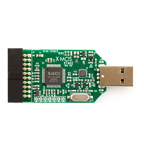
- Page 2 IDC XSYS USB Connector LQ64 Connector USB Transceiver To debug a board with the XTAG-2 you must use the XMOS Design Tools version 9.9 or later, available from the XMOS web site. 2 XS1-L1 Device The XTAG-2 is based on a single XS1-L1 device in a 64LQFP package. The XS1-L1 consists of a single XCore, which comprises an event-driven multi-threaded processor with tightly integrated general purpose I/O pins and 64 KBytes of on-chip RAM.
- Page 3 XTAG-2 Hardware Manual (1.0) 3 USB Connector The XTAG-2 uses a Standard-A type USB connector to link to a PC. Standard-A type USB Connector USB Transceiver (USB3318) The USB connector is connected to an SMSC USB3318 high-speed transceiver using a ULPI interface. The I/O pins for the USB transceiver are mapped to ports on the processor as described in the tables below.
- Page 4 XTAG-2 Hardware Manual (1.0) 4 XSYS Connector The XTAG-2 includes an XSYS 20-way IDC header, which can be used to connect it to an XMOS development board for debugging programs on the hardware. The XSYS connector provides pins for JTAG control, system reset, processor debug, a duplex UART link and a 2-bit serial XMOS Link.
- Page 5 19 20 4.1 UART configuration No UART hardware is provided. Instead, the UART is implemented in software by mapping the two UART pins to ports on the XS1-L device. The XTAG-2 performs a UART-to-USB conversion on these pins. UART_RX UART_TX The table below shows the pin-to-port mapping.
- Page 6 XTAG-2 Hardware Manual (1.0) 4.2 XMOS Link Configuration Some of the I/O pins on the processor are configured as a duplex 2-bit serial XMOS Link. The mapping of XMOS Link to the pins is shown in the table below: XMOS Link...
- Page 7 XTAG-2 Hardware Manual (1.0) 6 I/O Port-to-Pin Mapping The table below provides a full description of the port-to-pin mappings described throughout this document. Port Processor X0D0 P1A0 TDSRC X0D1 P1B0 TDSNK X0D2 P4A0 P8A0 X0D3 P4A1 P8A1 X0D4 P4B0 P8A2...
- Page 8 “Information”) and is providing it to you “AS IS” with no warranty of any kind, express or implied and shall have no liability in relation to its use. XMOS Ltd. makes no representation that the Information, or any particular implementation thereof, is or will be free from any claims of infringement and again, shall have no liability in relation to any such claims.
Need help?
Do you have a question about the XTAG-2 and is the answer not in the manual?
Questions and answers