
Related Manuals for Unidrive ZoneLogix 301216


Summary of Contents for Unidrive ZoneLogix 301216
- Page 1 Installation and Troubleshooting Guide ® ZoneLogix Smart Conveyor Control Part # 301216 ™ With IntelliZone Handling Technology ®...
-
Page 2: Table Of Contents
C O N T E N T S 1 Product Diagram 2 General Notes Motor Cable & Connection Header ......................5 +24V DC Power Input Connection Header .................... 5 PNP Sensor Connection Header ......................5 Smart User Input-Output Connection Header ..................5 LED Indicators .............................. - Page 3 L I S T O F F I G U R E S Figure 1: ZoneLogix Control Components ............4 ® Figure 2: Firmware Version Display Example ............. 10 Figure 3: ZIP Mode performance compared to ZPA Mode………………….……….11 L I S T O F T A B L E S Table 1: DC Power Inputs Pinout ................
-
Page 4: Product Diagram
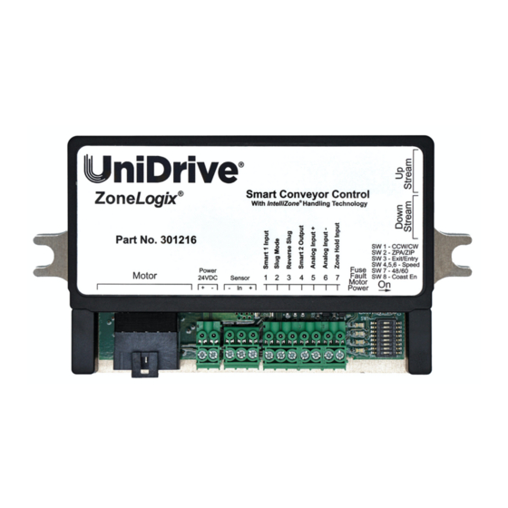
Product Diagram Logix Figure 1: Zone Control Components ® 1) Motor Connection Header 2) +24V DC Power Input Header (plug included) 3) PNP Sensor Connection Header (plug included) 4) Smart/User Input-Output Connection Header (plug included) 5) LED Indicators 6) Configuration Switches 7) Upstream Peer-to-Peer RJ-25 Connection 8) Downstream Peer-to-Peer RJ-25 Connection 9) Mounting Plate/Heat Sink... -
Page 5: General Notes
*NOTE: The +VDC signal for the + Pin is fused with a 0.1 UniDrive® motors and controls are designed to operate together as Amp self-resetting fuse. Use of this output for any purpose that requires more than 0.1 Amps will cause the fuse to a complete and compatible drive system. -
Page 6: Configuration Switches
Select the motor you will be using. Properly match the control’s motor selection to the motor that is actually being operated by the control. In addition to the standard 48 watt UniDrive® motor, this control Mounting Plate/Heat Sink provides increased performance with our 60 watt UniDrive motor with its higher operating speed. -
Page 7: Select A Speed
Select a Speed Configure the Rotation Three switches determine the operating speed, making it Identify the proper direction of rotation for the motor shaft simple to match speeds in multiple zones. The actual speed in order to move objects from the upstream (entry) end of selected also depends on the motor that you selected in the the conveyor towards the downstream (exit) end of the previous step, so set those switches first. -
Page 8: Connect User Input/Output
Analog Speed Control Input Connect User Input/Output 3.9.5 Entry Zone 3.9.1 Use the control’s Analog In+ and Analog In- inputs in combination to provide a 0-10 V differential signal that Use Smart 1 Input (a PNP input called request) to notify the overrides the settings of the speed control DIP switch. -
Page 9: Special Functions
During Power Up 4.3.1 Special Functions When power is first applied, each control goes through a self- check and reports its firmware revision as described in 5.2 Firmware Version Display. Beginning at the Exit end and then flowing zone by zone after very brief intervals to avoid creating high inrush current at the Configuring the Control as a BMC power supply, each zone then runs for a period of time (Run-... -
Page 10: Diagnostics & Troubleshooting
Firmware Version Display Diagnostics & Troubleshooting Three (3) of the feedback LEDs are used to communicate the firmware revision of the control assembly during the start-up sequence. Each time that power is applied to the board, the green (power) and red (fault) LEDs will turn on immediately. After LED Indicators 1.0 second the amber LED will flash on for 0.75 seconds followed by an off period. -
Page 11: Safety & Cautions/Warnings
The motor connector must not be used as a power on/off switch. The control and UniDrive motor are to be mounted in a location free from potential impact or other physical damage. 24VDC Power must be applied to the control with the proper polarity to avoid potentially damaging the control. -
Page 12: Application Related (Zpa Versus Zip Mode Performance)
Application Related – ZPA vs ZIP ZPA Mode (Standard Singulation) compared to ZIP Mode showing the increased parcel throughput possible in ZIP Mode Figure 3: ZIP Mode Performance compared to ZPA Mode ZoneLogix Control, ACG P/N 301216 July 23, 2021 Page 12...
Need help?
Do you have a question about the ZoneLogix 301216 and is the answer not in the manual?
Questions and answers