Advertisement
Quick Links
Advertisement

Subscribe to Our Youtube Channel
Related Manuals for Supermicro SUPER C9Z790-CG


Summary of Contents for Supermicro SUPER C9Z790-CG
- Page 1 C9Z790-CG C9Z790-CGW...
-
Page 3: About Standardized Warning Statements
The following statements are industry standard warnings, provided to warn the user of situations which can potentially cause a bodily injury. Should you have questions or experience difficulty, contact Supermicro's Technical Support De- partment for assistance. Only certified technicians should attempt to install or configure components. - Page 4 C9Z790-CG/-CGW QUICK REFERENCE GUIDE 限用物質含有情況標示聲明書 限 限 用 用 物 物 質 質 含 含 有 有 情 情 況 況 標 標 示 示 聲 聲 明 明 書 書 Declaration of the Presence Condition of the Restricted Substances Marking 設備名稱:主機板...
-
Page 5: Ami Bios Post Codes
AMI BIOS POST Codes AMI BIOS POST Codes About AMI BIOS POST Codes The table below lists some of AMI BIOS POST codes for this motherboard. For more information, refer to https://www. supermicro.com/manuals/other/AMI_AptioV_BIOS_POST_Codes_for_SM_Motherboards.pdf. Code Description 0x32 CPU post-memory initialization is started... - Page 6 C9Z790-CG/-CGW QUICK REFERENCE GUIDE M.2 Device/Heatsink Installation M.2 Device/Heatsink Installation M.2 Device/Heatsink Installation This motherboard has three PCIe M.2 M-key sockets that support the M.2 2260/2280/22110 modules (M.2-P1 and M.2- P2 only) and 2260/2280 modules (M.2-C1 only). Three standoffs are pre-installed in the posi- tion of 22110 mounting holes (M.2-P1 and M.2-P2 only) and 2280 mounting hole (M.2- C1 only).
- Page 7 C9Z790-CG/-CGW QUICK REFERENCE GUIDE M.2 Device/Heatsink Installation (Continued) M.2 Device/Heatsink Installation (Continued) 3. Installation WITH the pre-installed standoff: Insert the M.2 device into the M.2 socket at a 30-degree angle and press it down. Installation WITHOUT the pre-installed standoff: Install the standoff to the intended mounting hole first.
- Page 8 C9Z790-CG/-CGW QUICK REFERENCE GUIDE M.2 Device/Heatsink Installation (Continued) M.2 Device/Heatsink Installation (Continued) 4. Remove the thermal pad protective film from the M.2 heatsink. 5. To install the heatsink correctly, make Pogo Pin Contacts sure the pogo pin contacts are prop- erly touching the pogo pins on the motherboard.
-
Page 9: Audio Configuration
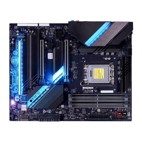
C9Z790-CG/-CGW QUICK REFERENCE GUIDE Audio Configuration Audio Configuration Audio Configuration 2 Channel 4.1 Channel 5.1 Channel 7.1 Channel Orange Center/Subwoofer Center/Subwoofer (Center/LFE Out) Black Rear Speaker Out Rear Speaker Out Rear Speaker Out (Surround) Light Blue Line In Line In Line In Side Speaker Out (Line In/Side Speaker Out) - Page 10 UPERMICR C9Z790-CG/-CGW . 1.0a uiCk efeRenCe uide Motherboard Layout and Features BACK PANEL I/O MAC CODE MAC CODE BAR CODE DP/HDMI HD AUDIO 22110 USB0/1/2/3 LAN2 LAN1 USB8 (3.2, 10Gb) USB6 (3.2, 10Gb) USB9 (3.2, 20Gb) USB7 (3.2, 20Gb) JLED_IO LED18 22110 LED17...
-
Page 11: Jumpers And Connectors
• One Supermicro Motherboard • One Quick Reference Guide • Four SATA Cables • One Driver CD • One S-Connector • Two Antennas (C9Z790-CGW only) • One I/O Shield Jumpers and Connectors Jumpers Jumper Description Default CLEAR CMOS... -
Page 12: Led Indicators
• www.supermicro.com (Email: support@supermicro.com) • Manuals: http://www.supermicro.com/support/manuals • Drivers & Utilities: https://www.supermicro.com/wdl/driver/ • Safety: http://www.supermicro.com/about/policies/safety_information.cfm LED Indicators LED Indicators Description Color/State Orange On: Bootable Device POST BOOT LED Bootable Device Power-On Self-Test (POST) Status Off: Bootable Device POST Completion... -
Page 13: Back Panel I/O Connectors
4400MT/s in four 288-pin memory slots. Populating these DIMM slots with a pair of memory modules of the same type and size will result in interleaved memory, which will improve memory performance. Notes: 1) For memory optimization, use only DIMM modules that have been validated by Supermicro. For the latest memory updates, please refer to our website at http://www.supermicro.com/products/motherboard. - Page 14 UPERMICR 美超微電腦股份有限公司 C9Z790-CG/-CGW 快速參考指南版本 1.0a 主機板元件配置圖 BACK PANEL I/O MAC CODE MAC CODE BAR CODE DP/HDMI HD AUDIO 22110 USB0/1/2/3 LAN2 LAN1 USB8 (3.2, 10Gb) USB6 (3.2, 10Gb) USB9 (3.2, 20Gb) USB7 (3.2, 20Gb) JLED_IO LED18 22110 LED17 JLED_POGO1 CPU_FAN2 SYS_FAN3 2280 2280...
- Page 15 單一主機板包裝盒內容清單 • Supermicro 主機板 x1 • 快速參考指南 • SATA 訊號線 x4 • 驅動程式光碟片 x1 • S- 轉接器 (S-Connector) x1 • 天線 x2 ( 僅限 C9Z790-CGW) • I/O 後擋板 跳線器/連接埠 跳線器 (Jumper) 跳線器 說明 預設值 CLEAR CMOS (板上) CMOS 組態資料清除開關 按鍵式開關...
- Page 16 線上技術支援及下載 • 聯絡我們 ( 技術支援信箱 ) : www.supermicro.com (Email: support@supermicro.com) • 產品手冊文件: http://www.supermicro.com/support/manuals • 驅動程式及工具程式: https://www.supermicro.com/wdl/driver/ • 產品安全性須知: http://www.supermicro.com/about/policies/safety_information.cfm LED 指示燈 LED 指示燈 說明 燈號顏色及狀態 開機硬碟 POST 狀態 橘燈:正在執行硬碟 POST 程序 BOOT LED * POST (Power-On Self-Test;開機自我檢測) 燈滅:完成硬碟 POST 程序...
- Page 17 請 安 裝 使 用 本 公 司 所 認 可 記 憶 體 模 組 以 達 記 憶 體 模 組 最 佳 化 。 更 多 記 憶 體 模 組 相 關 訊 息 ,請 參 閱 本 公 司 網 頁 http://www.supermicro.com/products/motherboard 。...
- Page 18 UPERMICR 美超微电脑股份有限公司 C9Z790-CG/-CGW 快速参考指南版本1.0a 主板布局和功能 I/O后面板 MAC CODE MAC CODE BAR CODE DP/HDMI HD AUDIO 22110 USB0/1/2/3 LAN2 LAN1 USB8 (3.2, 10Gb) USB6 (3.2, 10Gb) USB9 (3.2, 20Gb) USB7 (3.2, 20Gb) JLED_IO LED18 22110 LED17 JLED_POGO1 CPU_FAN2 SYS_FAN3 2280 2280 2280 2260 2260...
- Page 19 包装内容 • Supermicro主板x1 • 快速参考指南x1 • SATA线x4 • 驱动程序光盘x1 • S接口(S-Connector)x1 • 天线x2(仅限C9Z790-CGW) • I/O扩展板x1 跳线和接口 跳线 跳线 描述说明 默认 CLEAR CMOS 清除CMOS开关 按钮开关 针脚1-4:外置扬声器 扬声器/蜂鸣器 针脚3-4:蜂鸣器(默认) JPME2 Intel制造模式 针脚1-2:正常 JWD1 看门狗功能启用 针脚1-2:重置 POWER BUTTON 内部电源按钮 按钮开关 RESET BUTTON 板载系统重置按钮...
- Page 20 联系信息 • www.supermicro.com (Email: support@supermicro.com) • 产品手冊文件:http://www.supermicro.com/support/manuals • 驱动程序及工具: https://www.supermicro.com/wdl/driver/ • 产品安全性须知:http://www.supermicro.com/about/policies/safety_information.cfm LED指示器 LED 指示器 描述说明 颜色/状态 橙灯亮:可引导设备POST BOOT LED 可引导设备开机自检(POST)状态 熄灭:可引导设备POST 完成 黄灯亮:CPU POST CPU LED CPU POST状态 熄灭:CPU POST 完成 蓝灯亮:DIMM POST DIMM LED DIMM POST Status 熄灭:DIMM POST 完成...
- Page 21 备注 • 此快速参考指南中显示的图片,仅用于图示目的。您的组件可能和或不与此指 南中显示的图片完全相同。 • 有关跳线、接口、LED指示灯、内存支持和CPU/主板安装说明的详细信息,请 参阅用户手册第2章。 CPU和内存支持 C9Z790-CG/-CGW支持单个12代(最多8+8核)/13代(最多8+16核)Intel Core i9/i7/i5/i3、Pentium和Celeron 系列处理器(LGA 1700插口),Non-ECC UDIMM DDR5内存容量达128GB,四条288针内存插槽速度达4400MT/s。 将一对类型和大小相同的内存模块插入这些DIMM插槽会形成内存交错模式,从而提高内存性能。 备注:1)要进行内存优化,请仅使用经Supermicro验证的DIMM模块。如需最新内存更新信息,请访问我们的网站, 网址为http://www.supermicro.com/products/motherboard。 2)务必最后连接电源线,并在添加、移除或更换任何硬件组件之前断开电源线。 3)过热会严重损坏CPU和主板。始终确保冷却风扇正常工作,以防止CPU过热。 DIMM内存安装 朝向CPU DIMMA1(黑色插槽) DIMMA2(灰色插槽) DIMMB1(黑色插槽) DIMMB2(灰色插槽) 内存占用指南 安装内存模块时,应按照以下顺序插入 DIMM 插槽:DIMMA2、DIMMB2、 DIMMA1、DIMMB1。 • 为优化内存性能,请在主板上使用相同类型、大小和速度的(DDR5)内存。 • 当安装不同频率DIMM内存模组时,所有DIMM将以最低DIMM的速度运行。 推荐数量(平衡型) DIMMA1 DIMMB1 DIMMA2 DIMMB2 总系统内存...
- Page 22 UPERMICR C9Z790-CG/-CGW クイック参照ガイド 1.0a版 マザーボードのレイアウトと機能 I/O バックパネル MAC CODE MAC CODE BAR CODE DP/HDMI HD AUDIO 22110 USB0/1/2/3 LAN2 LAN1 USB8 (3.2, 10Gb) USB6 (3.2, 10Gb) USB9 (3.2, 20Gb) USB7 (3.2, 20Gb) JLED_IO LED18 22110 LED17 JLED_POGO1 CPU_FAN2 SYS_FAN3 2280 2280 2280 2260...
- Page 23 パッケージ内容 • Supermicro マザーボード 1枚 • クイック参照ガイド 1冊 • SATA ケーブル 4本 • ドライバーCD 1枚 • S-コネクタ 1個 • アンテナ 2本(C9Z790-CGW のみ) • I/O シールド 1個 ジャンパーおよびコネクタ ジャンパー ジャンパー 説明 デフォルト CMOSクリア CMOSクリアスイッチ ボタンスイッチ ピン 1~4:外部スピーカー スピーカー/ブザー ピン 3-4:ブザー (デフォルト) JPME2 Intelマニュファクチャーモード...
- Page 24 お問合せ先 • www.supermicro.com (Eメール:support@supermicro.com) • マニュアル:http://www.supermicro.com/support/manuals • ドライバー & ユーティリティ: https://www.supermicro.com/wdl/driver/ • 安全性: http://www.supermicro.com/about/policies/safety_information.cfm LED インジケーター LED インジケーター 説明 カラー/状態 オレンジ色に点灯:ブータブルデバイスPOST ブート LED ブータブルデバイスのパワーオンセルフテスト(POST)ステータス オフ:ブータブルデバイスPOST 完了 黄色に点灯:CPU POST CPU LED CPU POSTステータス オフ:CPU POST 完了 青色に点灯:DIMM POST DIMM LED DIMM POSTステータス...
- Page 25 • 本クイック参照ガイドにある図は参考用です。お手元のコンポーネントは、本ガイドに示され ている図と異なるか、まったく同一ではない可能性があります。 • 以下に関する詳細は第2章にあるユーザーマニュアルを参照してください:ジャンパー、コネ クタ、LEDインジケータ、メモリサポートおよびCPU/マザーボードインストールガイド。 CPU およびメモリサポート C9Z790-CG/-CGWは第12世代(最大8+8コア)/第13世代(最大8+16コア)Intel Core i9/i7/i5/i3、Pentium、Celeron シリー ズ プロセッサー(LGA 1700ソケット)、4つの288ピンメモリスロットで最大 4400MT/s を備えた最大128GBのバッファなし非ECC UDIMM DDR5メモリをサポートします。これらのDIMMスロットに、同一型の同じサイズのメモリモジュールを2枚装着すると、インターリーブメモリとなり、メモリ の性能が向上します。 備考:1) メモリの最適化には、Supermicro によって検証済みの DIMM モジュールのみを使用してください。最新のメモリアップデートにつ いては、当社のウェブサイト(http://www.supermicro.com/products/motherboard)を参照してください。 2) 電源コードは必ず最後につなげてください。ハードウェアコンポーネントを追加、取り外し、または変更する前には必ず抜いてください。 3) 過熱は、CPUとマザーボードに深刻な損傷を与える可能性があります。CPUを過熱から保護するため、冷却ファンが適切に機能して いることを常に確認してください。 DIMM メモリ設置 CPU の方向 DIMMA1 (ブラックのスロット) DIMMA2 (グレーのスロット) DIMMB1 (ブラックのスロット) DIMMB2 (グレーのスロット)
- Page 26 UPERMICR C9Z790-CG/-CGW 간편 가이드 개정판 1.0a 마더보드 레이아웃 및 특징 후면패널I/O MAC CODE MAC CODE BAR CODE DP/HDMI HD AUDIO 22110 USB0/1/2/3 LAN2 LAN1 USB8 (3.2, 10Gb) USB6 (3.2, 10Gb) USB9 (3.2, 20Gb) USB7 (3.2, 20Gb) JLED_IO LED18 22110 LED17 JLED_POGO1 CPU_FAN2 SYS_FAN3...
- Page 27 제품 구성물 • Supermicro 메인보드 1개 • 간편 가이드 1부 • SATA 케이블 4개 • 드라이버 CD 1개 • S-커넥터 1개 • 안테나 2개(C9Z790-CGW에만 해당) • I/O 쉴드 1개 점퍼 및 커넥터 점퍼 점퍼 설명 기본값 CMOS 초기화 CMOS 초기화 스위치...
- Page 28 연락처 정보 • www.supermicro.com(이메일: support@supermicro.com) • 사용 설명서: http://www.supermicro.com/support/manuals • 드라이버 및 유틸리티: https://www.supermicro.com/wdl/driver/ • 안전: http://www.supermicro.com/about/policies/safety_information.cfm LED 표시등 LED 표시등 설명 색/상태 주황색으로 켜짐: 부팅 가능한 장치 POST BOOT LED 부팅 가능한 전원 자체 테스트(POST) 상태 꺼짐: 부팅 가능한 장치 POST 완료...
- Page 29 ECC UDIMM DDR5 메모리를 지원합니다. 이러한 DIMM 슬롯을 유형 및 크기가 동일한 메모리 모듈 쌍으로 채우면 인터리브 메모리가 추가되어 메모리 성능이 향상됩니다. 참고: 1) 메모리 최적화를 위해 반드시 Supermicro의 인증을 받은 DIMM 모듈을 사용해야 합니다. 최신 메모리 업데이트 는, 저희 웹사이트 http://www.supermicro.com/products/motherboard참조하세요.
- Page 30 C9Z790-CG/-CGW QUICK REFERENCE GUIDE Notes Notes...
Need help?
Do you have a question about the SUPER C9Z790-CG and is the answer not in the manual?
Questions and answers