
Related Manuals for Computherm Q10Z


Summary of Contents for Computherm Q10Z
- Page 1 Q10Z COMPUTHERM zone controller (for controlling 1 to 10 heating zones) Operating Instructions - 1 -...
- Page 2 - 2 -...
- Page 3 1. A GENERAL DESCRIPTION OF THE COMPUTHERM ZONE CONTROLLER Q10Z Since in the boilers a connector has been installed only for one room ther- mostat, a zone controller is needed to divide the heating network into zones, to control zone valves and to operate the boiler from several thermostats. The...
- Page 4 The figure below shows an example of dividing the heating system into zones: For the sake of energy saving, it is recommended that comfort temperature is set only in those rooms and in those periods which and when are being used, because an every temperature reduction of 1 °C results in 6 percent energy savings during a heating season.
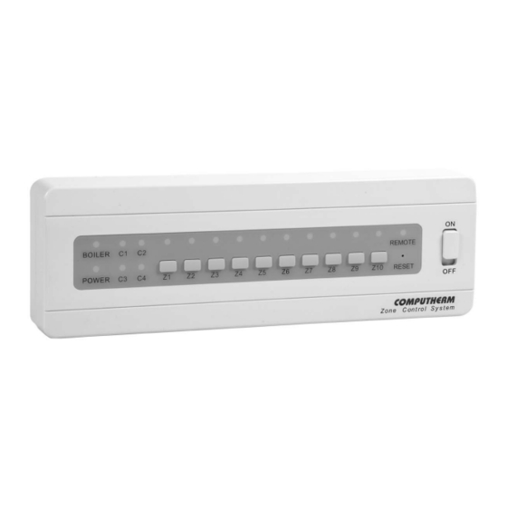
- Page 5 All 10 zones have a connection point to a room thermostat, a valve controller output and a pump controller output. The NO-COM output points of the poten- tial-free room thermostats should be connected to the thermostat connection points (T1 to T10) of the zones. Each of the valve outputs (VALVE ZONE 1 to ZONE 10) has a fixed neutral conductor (N), a switched phase (L) and a fixed phase (FL) connection points (to operate some zone valve adjustment motors a fixed phase connection point is also required).
- Page 6 Attention! We recommend that you establish the heating system to be reg- ulated with the zone controller so that the heating me- Q10Z COMPUTHERM dium can circulate even when all zone valves are in closed position and a circulating pump is on. This can be done either by a permanently open heating circuit or installing a by-pass valve.
- Page 7 To put the zone controller into operation follow the steps below: • Loosen the screws on the lower edge of the box of the device and se- parate the cover plate from the base plate. Then the connectors of the thermostats, zone valves, pump(s), the boiler and the network cable be- come accessible.
- Page 8 The zone controller has a common potential-free output (NO-COM) as well, which normally (when all thermostat connected to the zone controller give switch-off command) is in open position This output will get into closed posi- tion when at least one thermostat gives a switch-on command, thereby start- ing the heating/cooling device connected thereto.
- Page 9 REMOTE function. When you connect a remotely controllable ther- mostat (e.g. a Wi-Fi thermostat) to these connection points COMPUTHERM then by modifying the set temperature of the thermostat remotely the whole heating system can be switched to an “away” (e.g. frost-free) temperature then can be reset to the normal (e.g.
-
Page 10: Technical Data
TECHNICAL DATA ─ Supply voltage: 230 V AC; 50 Hz ─ Standby power consumption: max 0.5 W ─ Voltage of zone outputs and common outputs: 230 V AC; 50 Hz ─ Loadability of zone outputs and common outputs: 2 A (0.5 A inductive load) Attention! Ensure that the com- bined load of 2 outputs belong- ing to a zone does not exceed... - Page 11 - 11 -...
- Page 12 MANUFACTURER: H-6726 Szeged, Fülemüle u. 34 Phone: +36 62 424 133 • Fax: +36 62 424 672 E-mail: iroda@quantrax.hu Web: www.quantrax.hu • www.computherm.info ORIGIN: designed in the EU, manufactured in China Copyright © Quantrax Kft. All rights reserved. - 12 -...
Need help?
Do you have a question about the Q10Z and is the answer not in the manual?
Questions and answers