Advertisement
Quick Links
Advertisement

Related Manuals for Computherm Q4Z


Summary of Contents for Computherm Q4Z
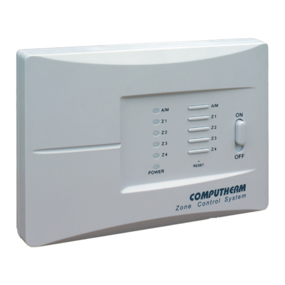
- Page 1 COMPUTHERM zone controller (for controlling 1 to 4 heating zones) Operating Instructions...
- Page 3 (Z1; Z2; Z3; Z4, Z1-2; Z3- 4; Z1- 4) associated with the thermostats. The COMPUTHERM Q4Z zone controllers can control 1 to 4 heating / cooling zones, which are regulated 1-4 switch-operated thermostats. The zones can operate independently from each other or, in case of need, all zones can operate at the same time.
- Page 4 An example of dividing the heating system into zones is shown in the figure below: boiler living room bedroom 1 bedroom 2 230 V AC floor heat. distr. distributor floor h. distributor collector manifold floor heat. collect. floor h. manifold From both a comfort and an energy-efficiency point of view, it is recommended to activate more than one switch for each day.
- Page 5 • The 1st and 2nd zones, beside their regular connection points, also have a joint connection point for a zone valve/pump (Z1-2). If any of the 1st two thermostats (T1 and/or T2) switches on, then beside the 230 V AC voltage appearing at Z1 and/or Z2, 230 V AC voltage appears on Z1-2 too, and the zone valves/pumps connected to these connection points open/start.
- Page 6 Attention! We recommend that you design the heating system you want to control with the COMPUTHERM Q4Z zone controller so that the heating medium can circulate in the closed position of all zone valves when a circulating pump is switched on.
- Page 7 thermostats, the zone valves/pumps, the boiler and the power supply are accessible. • Select the location of the zone controller near the boiler and/or the manifold and create the holes on the wall for installation. • Secure the zone controller board to the wall using the supplied screws. •...
- Page 8 circuit). If there are no such zones, then in order to prevent the heating system from an event in which all heating circuits are closed but a pump is switched on, the zone controller has two types of delay function. 5.1 Turn on delay If this function is activated and the outputs of the thermostats are switched off, then in order to open the valves of the given heating circuit before starting the...
- Page 9 5.3 Activating/deactivating of the delay functions To activate/deactivate the Turn on and off delay functions, press and hold the Z1 and Z2 buttons on the zone controller for 5 seconds until the blue LED flashes at one second intervals. You can activate/deactivate the functions by pressing the buttons Z1 and Z2.
-
Page 10: Technical Data
TECHNICAL DATA ‒ Supply voltage: 230 V AC, 50 Hz ‒ Standby power consumption: 0,15 W ‒ Voltage of the zone outputs: 230 V AC, 50 Hz ‒ Loadability of the zone outputs: 2 A (0.5 A inductive load) ‒ Switchable voltage of the 230 V AC, 50 Hz relay that controls the boiler: ‒... - Page 12 LVD 2014/35/EU and RoHS 2011/65/EU. QUANTRAX Ltd. Manufacturer: H-6726 Szeged, Fülemüle u. 34., Hungary Telefon: +36 62 424 133 • Fax: +36 62 424 672 E-mail: iroda@quantrax.hu Web: www.quantrax.hu • www.computherm.info Origin: China Copyright © 2020 Quantrax Ltd. All rights reserved.
Need help?
Do you have a question about the Q4Z and is the answer not in the manual?
Questions and answers