Table of Contents
Advertisement
Quick Links
Advertisement
Table of Contents

Related Manuals for Milesight Ultra Series


Summary of Contents for Milesight Ultra Series
- Page 1 Industrial Router Ultra Series UR75 User Guide...
- Page 2 Safety Precautions Milesight will not shoulder responsibility for any loss or damage resulting from not following the instructions of this operating guide. The device must not be disassembled or remodeled in any way. To avoid risk of fire and electric shock, do keep the product away from rain and moisture before ...
- Page 3 Revision History Date Doc Version Description Nov. 25, 2022 V 3.0 Initial version based on hardware 3.x 1. Web GUI Design Change 2. Add LT2P and PPTP VPN client feature Jan. 17, 2023 V 3.1 3. Add VLAN feature 4. Add HTTPS certificate import feature...
-
Page 4: Table Of Contents
Contents Chapter 1 Product Introduction ........................6 1.1 Overview ............................6 1.2 Advantages ............................6 Chapter 2 Hardware Introduction ......................... 7 2.1 Packing List ............................7 2.2 Hardware Overview .......................... 8 2.3 Serial & IO & Power Pinouts ......................9 2.4 LED Indicators ..........................9 2.5 Dimensions (mm) ...........................10 2.6 Reset Button ........................... - Page 5 6.2.2 WLAN (Wi-Fi Version Only) ....................47 6.2.3 Firewall ..........................48 6.2.3.1 General Settings ....................... 48 6.2.3.2 ACL ..........................49 6.2.3.3 Port Mapping (DNAT) ....................51 6.2.3.4 DMZ ........................... 52 6.2.3.5 Custom Rules ......................52 6.2.3.6 Certificates ........................53 6.2.4 Static Routes ........................53 6.2.5 Diagnostics ..........................
-
Page 6: Chapter 1 Product Introduction
Chapter 1 Product Introduction 1.1 Overview UR75 is an industrial cellular router with embedded intelligent software features that are designed for multifarious M2M/IoT applications. Upgraded to the latest cellular technology - 5G, the UR75 makes it possible to enjoy ultra-fast broadband access with a 5G cellular network. Adopting high-performance and low-power consumption industrial grade CPU and wireless module, the UR75 is capable of providing a wire-speed network with low power consumption and an ultra-small package to ensure an extremely safe and reliable connection to the wireless network. -
Page 7: Chapter 2 Hardware Introduction
Support policy routing and NAT for more secure intranet access Easy Maintenance Milesight DeviceHub provides easy setup, mass configuration, and centralized management of remote devices The user-friendly web interface design and several upgrade options help administrator to manage... -
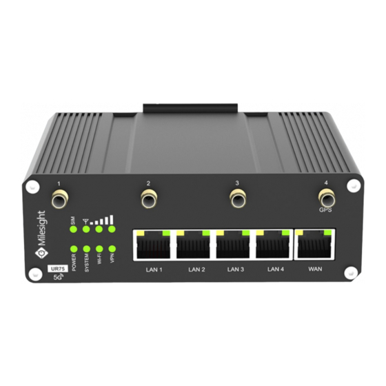
Page 8: Hardware Overview
4 × Stubby Wi-Fi 4 × Stubby Cellular Antenna Magnetic Antennas (Wi-Fi 1 × GPS Antenna Antennas Mounts (Optional) Version only) 1 × Quick Guide 1 × Warranty Card If any of the above items is missing or damaged, please contact your sales representative. 2.2 Hardware Overview A. -
Page 9: Serial & Io & Power Pinouts
2.3 Serial & IO & Power Pinouts RS232 RS485 Description Digital Input Ground Data - Transmit Data Common Ground Digital Output Data + Receive Data Description Wire Color Positive Negative Black 2.4 LED Indicators Indication Status Description The power is switched off Power &... -
Page 10: Dimensions (Mm)
2.5 Dimensions (mm) 2.6 Reset Button The reset button is beside SIM slots. Description Function SYSTEM & SIM Action Static Press and hold the reset button for more than 5 seconds. Reset Static → Blinking Release the button and wait. Off →... -
Page 11: Device Installation
3.3 Device Installation UR75 device can be placed on a desktop or mounted to a DIN rail. For DIN rail mounting, use 2 pcs of M3 × 6 flat head Phillips screws to fix the mount clip to the device, and then hang the device to the DIN rail. -
Page 12: Chapter 4 Access To Web Gui
Chapter 4 Access to Web GUI UR75 provides user-friendly web GUI for configuration and users can access it via LAN port. This chapter explains how to access to Web GUI of the UR75 router. Username: admin Password: password IP Address: 192.168.1.1 Connect PC to LAN port or USB port of U75 router directly. - Page 13 3. Open a Web browser on your PC (Chrome is recommended), type in the IP address 192.168.1.1 to access the web GUI, then enter the default username and password, and click Login. If you enter the username or password incorrectly more than 5 times, the login page will be locked for 10 minutes.
-
Page 14: Chapter 5 Application Examples
Chapter 5 Application Examples 5.1 Configure Cellular Connection UR75 routers have two cellular interfaces SIM1 & SIM2. Only one cellular interface is active at a time. We are about to take an example of inserting a SIM card into the SIM1 slot of the UR75 and configuring the router to get access to the Internet through cellular. - Page 15 Go to Network > Interface > Link Failover to enable correspond SIM and drag the buttons to change link priority. Click Edit of a link to configure ICMP ping detection information. When ping probe is enabled, the router will send ICMP packets to detection server to check if this link is valid. If no response and exceeding max retries, it will switch to the lower priority link.
-
Page 16: Configure Ethernet Connection
Go to Status > Cellular to check the status of the cellular connection. If modem status is ready and network status shows Connected, the SIM has been dialed up successfully. Related Topic Cellular Setting Cellular Status 5.2 Configure Ethernet Connection UR75 routers support getting network access via WAN port. - Page 17 3. Go to Network > Interface > Link Failover to enable WAN and drag the button to change link priority. 4. Click Edit of a link to configure ICMP ping detection information. When ping probe is enabled, the router will send ICMP packets to detection server to check if this link is valid. If no response and exceeding max retries, it will switch to the lower priority link.
-
Page 18: Configure Wi-Fi Access Point
5. Click Network > Diagnostics to check the network connectivity. Related Topic WAN Setting 5.3 Configure Wi-Fi Access Point UR75 routers support both 2.4G and 5G Wi-Fi and they can work as access points to provide network access to other devices at the same time. We are about to take an example of configuring a 2.4G Wi-Fi access point. -
Page 19: Configure Openvpn Client
Use a smart phone to connect the access point of UR75. You can check the information of the connected client/user on Status > Overview page. Related Topic WLAN Setting 5.4 Configure OpenVPN Client UR75 routers can work as OpenVPN clients or OpenVPN servers. We are about to take an example of configuring OpenVPN client to connect to OpenVPN cloud. - Page 20 3. Select the location as OpenWrt and download the OVPN file. 4. Go to VPN > OpenVPN > OpenVPN Client page of UR75, select configuration method as File Configuration, then import the OVPN file. 5. Go to Status > VPN page to check if the client is connected.
-
Page 21: Configure Nat Rule
You can also check the connection status on OpenVPN cloud. 6. You can remotely get access to this router via OpenVPN Connect software. If you need to access the terminal devices under UR75 subnet, it’s necessary to assign the subnet on OpenVPN cloud. Related Topic OpenVPN Client 5.5 Configure NAT Rule... -
Page 22: Configure Serial Dtu Connection
Related Topic Port Mapping 5.6 Configure Serial DTU Connection Example A PLC is connected with the UR75 via RS232 and need to transfer the data to a remote TCP server transparently. Configuration Steps Go to Industrial > Serial Port, enable Serial 1 and configure serial port parameters. The serial port... - Page 23 parameter shall be kept in consistency with those of PLC, as shown in figure below. Configure Serial Mode as DTU Mode and protocol as TCP Client. Configure TCP server IP and port Start TCP server on PC. Take Netassist test software as example. Make sure port mapping is done.
- Page 24 Connect the UR75 to PC via RS232 for PLC simulation. Then start sscom software on the PC to test communication through serial port. After connection is established between the UR75 and the TCP server, you can send data between sscom and Netassit. PC side TCP server side...
-
Page 25: Restore Factory Defaults
After serial communication test is done, you can connect PLC to RS232 port of the UR75 for test. Related Topic Serial Port 5.7 Restore Factory Defaults Method 1: Go to System > Backup/Upgrade page, click Perform Reset button, you will be asked to confirm if you’d like to reset it to factory defaults. -
Page 26: Firmware Upgrade
5.8 Firmware Upgrade It is suggested that you contact Milesight technical support first before you upgrade the device. After getting the image file please refer to the following steps to complete the upgrade. Go to System > Backup/Upgrade page, and click Flash image…. -
Page 27: Chapter 6 Web Configuration
After upload, click Continue to upgrade the device. When SYS LED changes from orange to green and stay statically, the upgrade is completed. Do not perform any operation or disconnect the power during the upgrade. Related Topic Backup / Flash Firmware Chapter 6 Web Configuration 6.1 Status 6.1.1 Overview... - Page 28 System Item Description The hostname of device, it can be modified on System > System > Hostname General Settings. Model The model name of the device. The serial number of the device. Firmware Version The current firmware version of the device. Hardware Version The current hardware version of the device.
-
Page 29: Cellular
The Active DHCP Leases tab displays the basic information of connected devices. Active DHCP Leases Item Description Hostname The hostname of the connected device. IPv4-Address Tthe IPv4 address of the connected device. MAC-Address The MAC address of the connected device. Remaining Lease The time remaining for this lease. - Page 30 Modem Information Item Description Status Corresponding detection status of module and SIM card. Module Model The model name of cellular module. Version The firmware version of cellular module. Current SIM The current SIM card used. Cellular Band The cellular band which the router used to register to network. Signal Strength The RSSI (Received Signal Indicator) of registered cellular network.
- Page 31 Register Status The registration status of SIM card. IMEI The IMEI of the cellular module. IMSI The IMSI of the SIM card. ICCID The ICCID of the SIM card. The network provider which the SIM card registers on. Network Type The connected network type, such as LTE, 3G, etc.
-
Page 32: Gps
Total data volume and packets of this month. 6.1.3 GPS When GPS function is enabled and the GPS information is obtained successfully, you can view the latest GPS information including GPS time, latitude, longitude and speed on this page. GPS Status Item Description Status... -
Page 33: Routing Table
Firewall Status Item Description Table: Filter The default table for handing network packets. Used to alter packets that create a new connection and Table: NAT used for Network Address Translation (NAT). Table: Mangle Used for specific types of packet alternation. Show/Hide Empty Chain Show/hide the chain without any rule. -
Page 34: Vpn
Item Description Active IPv4/IPv6 Router Interface The outbound interface of the route. Destination The IP address and netmask of destination host or destination Network network. IPv4/IPv6 The IP address of the gateway to send packets from. Gateway Priority The metric number indicating interface priority of usage. ARP Cache IPv4 Address The IP address of ARP pool. -
Page 35: Network
VPN Status Item Description Clients Name The name of the enabled VPN clients. Status The connection status of client. Local IP The local IP address and subnet of the VPN tunnel. Remote IP The real remote IP address and subnet of the VPN tunnel. IPsec/OpenVPN Server Status The status of Server. -
Page 36: Wan
Global Network Options Item Description IPv6 ULA-Prefix The IPv6 unique local address (ULA) prefix of this device. 6.2.1.1 WAN The WAN port can be connected with an Ethernet cable to get Internet access. It supports 3 connection types which can work with both IPv4 and IPv6. - Static IP: configure IPv4 address, netmask and gateway for Ethernet WAN interface. - Page 37 Static Address - General Settings Item Description Default IP Type It’s fixed as IPv4. IPv4 IPv4 Address Set the IPv4 address of the WAN port. IPv4 Netmask Set the Netmask for WAN port. 255.255.255.0 IPv4 Gateway Set the gateway for WAN port's IPv4 address. IPv4 Primary DNS Set the primary IPv4 DNS server.
- Page 38 DHCP Client - Advanced Settings Item Description Obtain DNS server Obtain peer DNS automatically. DNS is necessary when automatically visiting domain name. Set the maximum transmission unit. Range: 68-1500. 3. PPPoE/PPPoEv6 PPPoE refers to a point to point protocol over Ethernet. If IPv6 negotiation is enabled, router can get both IPv4 and IPv6 address.
-
Page 39: Lan/Dhcp Server
PPPoE - Advanced Settings Item Description Obtain IPv6-Address Enable IPv6 negotiation on the PPP link. Obtain DNS server Obtain peer DNS automatically during PPP dialing. DNS is necessary automatically when visiting domain name. Max Retries Set the maximum retry times after it fails to dial up. Range: 0-9. Heartbeat Interval (s) Set the heartbeat interval for link detection. - Page 40 LAN - General Settings Item Description Uptime: how long has the device been running. MAC: MAC address of LAN interfaces. Status RX: the data volume and packets received in this interface. TX: the data volume and packets transmitted from this interface. IPv4/IPv6: IPv4/IPv6 address of LAN interfaces.
-
Page 41: Cellular
(2m). Set to override the netmask sent to clients. Normally it is IPv4-Netmask calculated from the subnet that is served. DNS Server Set the DNS server list for clients. DHCP Server-IPv6 Settings Item Description Choose to enable DHCPv6 server when using cellular Enable IPv6 or PPPoE v6. -
Page 42: Interface Settings
Cellular Item Description Select SIM Select the SIM card you need to configure the settings. Card Show the Internet protocol type to use for this interface. IP Type Option: IPv4, IPv6 and IPv4/IPv6. Enter the Access Point Name for cellular dial-up connection provided by local ISP. -
Page 43: Link Failover
Interface Setting Item Description Interface Users can define the Ethernet ports according to their needs. Set the status of Ethernet port; select Up to enable and Down to Status disable. Property The Ethernet port's type, fixed as a WAN port or a LAN port. Interface Speed Ethernet port speed is fixed as Auto. - Page 44 Display the IP address of the interface. Drag this button to adjust the priority of network links. The top of the list has the highest priority. Edit Click to edit ping probe settings of every network link. Settings Revert to high When enabled, periodically detect whether the high-priority link priority link can be pinged, and if so, switch the link with a higher priority.
-
Page 45: Switch (Vlan)
response to a ping request. If it does not receive a response for the amount of time predefined in this field, the ping request will be considered as fail. The retry times of the router sending ping request until Max Retries determining that the connection has failed. -
Page 46: Static Ip Address Assignment
Switch - DHCP Server Item Description Enable to disable DHCP for this VLAN interface. The DHCP server Enable can only be deleted when you deleted corresponding LAN settings, Interface Show the VLAN interface name of the DHCP server. Define the beginning of the pool of IP addresses which will be leased Start Address to DHCP clients. -
Page 47: Wlan (Wi-Fi Version Only)
IPv4 Address The IPv4 address assigned to the client. IPv4 Lease time Time remaining for the client. 6.2.2 WLAN (Wi-Fi Version Only) This section explains how to set the related parameters for Wi-Fi network. UR75 supports both 2.4G and 5G Wi-Fi and they can work at the same time. WLAN Item Description... -
Page 48: Firewall
Broadcast and users have to enter the SSID manually to access to the wireless network. When AP isolation is enabled, all users that access to the AP are isolated AP Isolation without communicating with each other. Max Client Type the max client number that the access point supports, range: 1-128. Number MAC Filtering MAC Filtering... -
Page 49: Acl
General Setting Item Description Default Security Configuration Enable/disable SYN-flood protection. SYN-flood protection allows to protect from a DDoS attack Enable SYN-flood that exploits part of the normal TCP three-way Enable Protection handshake to consume resources on the targeted server and render it unresponsive. Log in using HTTPS Log in the web GUI of device via HTTPS by default. - Page 50 Item Description The packets which are not included in the access control list will be processed by the default filter policy. Default Filter Policy Accept: allow all traffic out of devices under LAN ports. Drop: deny all traffic out of devices under LAN ports. Enable Enable this ACL rule.
-
Page 51: Port Mapping (Dnat)
ACL - Add/Edit Name Define a unique name for this ACL rule. Type Select type as IPv4 or IPv6. Protocol Select protocol among TCP, UDP and ICMP. Select the source interface type from Device Output, LAN, VLAN or Source Interface WAN (WAN, Cellular, WLAN). -
Page 52: Dmz
receiving from the incoming interface. Enter the port or port range that packets are forwarded to after Internal Port receiving from the incoming port(s). When setting port range, the value should be the same as external port range. Enable Enable or disable this port mapping rule. Drag this button to adjust the priority of port mapping rules. -
Page 53: Certificates
6.2.3.6 Certificates In this page, you can import the HTTPS certificates for router web GUI secure access. 6.2.4 Static Routes A static routing is a manually configured routing entry. Information about the routing is manually entered rather than obtained from dynamic routing traffic. After setting static routing, the package for the specified destination will be forwarded to the path designated by users. -
Page 54: Vpn
Network Utilities Item Description IPv4 Ping Click to ping outer network from the device in IPv4. IPv6 Ping Click to ping outer network from the device in IPv6. IPv4 Traceroute Address of the destination host to be detected in IPv4. IPv6 Traceroute Address of the destination host to be detected in IPv6. - Page 55 OpenVPN Server - File Configuration Item Description Click to browse the server configuration ovpn format file including the settings and Browse certificate contents. Please refer to the server configuration file according to sample: server.conf Edit Click to edit the imported file. Export Export the server configuration file.
- Page 56 OpenVPN Server - Page Configuration Item Description Protocol Select a transport protocol used by connection from UDP and TCP. Enter the local hostname or IP address for bind. If left blank, OpenVPN Listening IP server will bind to all interfaces. Enter the TCP/UCP service number for OpenVPN client connection.
-
Page 57: Openvpn Client
Note: please adjust log severity to Info if you need to connect many clients. Enable CRL Enable or disable CRL verify. Enable Client to Client When enabled, openVPN clients can communicate with each other. Allow multiple clients to connect with the same common name or Enable Dup Client certification. - Page 58 OpenVPN Client - File Configuration Item Description Click to browse the client configuration ovpn format file including the settings and Browse certificate contents. Please refer to the client configuration file according to sample: client.conf Edit Click to edit the imported file. Export Export the server configuration file.
- Page 59 OpenVPN Client - Page Configuration Item Description Protocol Select a transport protocol used by connecting UDP and TCP. Remote IP Address Enter remote OpenVPN server's IP address or domain name. Enter the TCP/UCP service number of remote OpenVPN server. Range: Port 1-65535.
-
Page 60: Certificate
AES-192-CBC and AES-256-CBC. Enter the maximum transmission unit. Range: 128-1500. Max Frame Size Set the maximum frame size. Range: 128-1500. Verbose Level Select from ERROR, WARING, NOTICE and DEBUG. User can enter some initialization strings in this field and separate the Expert Options strings with semicolon. -
Page 61: Ipsecvpn
6.3.2 IPsecVPN IPsec is especially useful for implementing virtual private networks and for remote user access through dial-up connection to private networks. A big advantage of IPsec is that security arrangements can be handled without requiring changes to individual computer. IPsec provides three choices of security service: Authentication Header (AH), Encapsulating Security Payload (ESP), and Internet Key Exchange (IKE). - Page 62 Select the identifier type, and send it to remote peer. Default: None ID: use local subnet IP address as ID Local ID Type FQDN: fully qualified domain name, example: test.user.com User FQDN: fully qualified username string with email address format, example: test@user.com Remote Subnet Set the remote LAN subnet on the IPsec tunnel.
-
Page 63: Ipsec Client
Negotiation Mode When using IKEv1, select Main or Aggressive. Encryption Algorithm Select DES, 3DES, AES128, AES192 or AES256. Authentication Algorithm Select MD5, SHA1 or SHA2-256. DH Group Select MODP768_1, MODP1024_2 or MODP1536_5. Select PSK or CA. PSK: use pre-shared key to complete the authentication. Local Authentication CA: use certificate to complete the authentication. - Page 64 IPsec Client Item Description Enable or disable IPsec client mode. A maximum of 3 Enable tunnels is allowed. IP Gateway Address Enter the remote IPsec server address. IPsec Mode Select Tunnel or Transport. IPsec Protocol Select ESP or AH. Local Subnet Enter the local LAN subnet IP address on the IPsec tunnel.
- Page 65 local ID. Default: None ID: use remote subnet IP address as ID FQDN: fully qualified domain name, example: test.user.com User FQDN: fully qualified username string with email address format, example: test@user.com SA Encryption Algorithm Select AES128, AES192 or AES256. SA Authentication Select SHA1 or SHA2-256.
-
Page 66: Certificate
Item Description IKE Version Select the method of key exchange of IKEv1 or IKEv2. Negotiation Mode When using IKEv1, select Main or Aggressive. Encryption Algorithm Select DES, 3DES, AES128, AES192 or AES256. Authentication Algorithm Select MD5, SHA1 or SHA2-256. DH Group Select MODP768_1, MODP1024_2 or MODP1536_5. -
Page 67: L2Tp
6.3.3 L2TP Layer Two Tunneling Protocol (L2TP) is an extension of the Point-to-Point Tunneling Protocol (PPTP) used by an Internet service provider (ISP) to enable the operation of a virtual private network (VPN) over the Internet. - Page 68 L2TP Item Description Enable Enable or disable L2TP client. Server IP Address Enter remote L2TP server's IP address or domain name. Username Enter the username that L2TP server provides. Password Enter the password that L2TP server provides. Authentication Type Select authentication type used to secure data sessions. Global Traffic All the data traffic will be sent out via L2TP VPN tunnel when this function Forwarding...
-
Page 69: Pptp
User can enter some initialization strings in this field and separate the Expert Options strings with semicolon. 6.3.4 PPTP Point-to-Point Tunneling Protocol (PPTP) is a protocol that uses a TCP control channel and a Generic Routing Encapsulation tunnel to encapsulate PPP packets. -
Page 70: Industrial Interface
PPTP Item Description Enable Enable or disable PPTP client. Server IP Address Enter remote PPTP server's IP address or domain name. Username Enter the username that PPTP server provides. Password Enter the password that PPTP server provides. Authentication Type Select authentication type used to secure data sessions. Global Traffic All the data traffic will be sent out viaPPTP VPN tunnel when this function Forwarding... -
Page 71: Serial Port
6.4.1 Serial Port This section explains how to configure serial port parameters to achieve communication with serial terminals, and configure work mode to achieve communication with the remote data centers, so as to achieve two-way communication between serial terminals and remote data centers. Serial Setting Item Description... - Page 72 Modbus Master: In Modbus Master mode, go to Industrial > Modbus Master to configure basic parameters and channels. DTU Mode Item Description Default Select from below protocols: TCP Client: the router is used as TCP client and transmits data to TCP server transparently.
- Page 73 Note: data will be sent out to public network when real serial data size reaches the preset packet size, even though it's within the serial frame interval. TCP/UDP Client After TCP client is connected with TCP server, the client will send Keepalive heartbeat packet by TCP regularly to keep alive.
-
Page 74: I/O
Max Retries Set the maximum retry times after it fails to read. Related Configuration Example DTU Application Example 6.4.2 I/O 6.4.2.1 DI This section explains how to configure monitoring condition on digital input, and take certain actions once the condition is reached. Item Description Enable... -
Page 75: Modbus Master
6.4.2.2 DO This section describes how to configure digital output mode. Item Description Enable Enable or disable DO. Select the working mode of DO. High Level: trigger the DO to send high level signal. Mode Low Level: trigger the DO to send low level signal. Counter: trigger the DO to send pulses. -
Page 76: Channel
Modbus Master Item Description Default Enable Enable/disable Modbus master. Set the interval for reading remote channels. When the read cycle ends, the commands which haven't been sent out will Read be discard, and the new read cycle begins. If it is set as 0, Interval the device will restart the new read cycle after all channels have been read. -
Page 77: Gps
Channel Setting Item Description Name Set the name to identify the remote channel. It cannot be blank. Slave ID Set Modbus slave ID. Address The starting address for Modbus reading. Number The reading quantity from starting address. Command Read command data type, options are Coil, Discrete, Holding Register (INT16), Type Input Register (INT16), Holding Register (INT32) and Holding Register (Float). -
Page 78: Gps Ip Forwarding
6.4.4.1 GPS IP Forwarding GPS IP forwarding means that GPS data can be forwarded over the Internet. GPS IP Forwarding Item Description Default Enable Forward the GPS data to the client or server. Disable Type Select connection type of the router as Client or Server. Client Protocol Select protocol of data transmission as TCP or UDP. -
Page 79: Gps Serial Forwarding
server. The range is 1-16. Local Port Set the router listening port when using as a Server. Range: 1-65535. Reconnect When the connection failes, router will reconnect to the server at the Interval preset interval. The range is 10-60 s. The device will send GPS data to the server/client according to this Report Interval interval if it reaches the stable decision threshold. -
Page 80: System
GPS Serial Forwarding Item Description Default Enable Forward the GPS data to the preset serial port. Disable Select the serial port to receive GPS data. Ensure that the Serial Type serial port is enabled on Industrial > Serial Port. The device will forward the GPS data to the serial port Report Interval according to this interval. -
Page 81: System
6.5.1 System System - General Setting Item Description Hostname Define the device name, needs to start with a letter. Local Time Show the current system time. Timezone Click the drop-down list to select the time zone you are in. Select the time synchronization mode. Sync Browser Time: Synchronize time with browser. -
Page 82: Password
Enter the new password again. 6.5.3 Device Management 6.5.3.1 Device Management You can connect the device to the Milesight DeviceHub management platform on this page so as to DeviceHub User Guide manage the device centrally and remotely. For more details, please refer to... -
Page 83: Cloud Vpn
Show the connection status between the device and the Status DeviceHub. Server Address IP address or domain of the DeviceHub management server. Select activation method to connect the device to the Activation Method DeviceHub server, options are "By Authentication Code" and "By Account name". -
Page 84: Backup / Upgrade
MilesightVPN. Local IP Show the virtual IP of the router. Remote IP Show the virtual IP of the Milesight VPN server. Show the information on how long has the router been Connection Time connected to the Milesight VPN. -
Page 85: Reboot
Related Configuration Example Firmware Upgrade Restore Factory Defaults 6.5.5 Reboot This page allows to reboot the device immediately or regularly. Reboot Item Description Reboot Now Reboot the device immediately. Schedule Enable Click to enable reboot schedule. Cycles Reboot the device at a scheduled frequency. Time Select the time to execute the schedule. - Page 86 Log Control - General Settings Item Description External system log Fill in the remote log server address (IP/domain name) which server the router sends. External system log Fill in the remote log server port which the router sends. server port External system log Choose UDP or TCP from the drop-down list to transmit log file server protocol...
-
Page 87: Debugger
Log Control - Advanced Settings Item Description AP log Download Click to download the last AP log recorded. Tcpdump log Start Click to start recording tcpdump log. Stop Click to stop recording tcpdump log. Download Click to download the last tcpdump log recorded. 6.5.7 Debugger 6.5.7.1 Cellular Debugger This tool allows to use AT commands to check cellular debug information. - Page 88 [END]...
Need help?
Do you have a question about the Ultra Series and is the answer not in the manual?
Questions and answers