Advertisement
Quick Links
Advertisement

Related Manuals for VIVOHOME VH869


Summary of Contents for VIVOHOME VH869
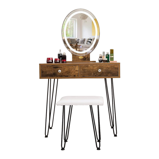
- Page 1 LIGHTED VANITY SET WITH GOLDEN LEGS Assembly Instructions...
- Page 2 Attention For safety and stability, we suggest you have to secure the anti-tip accessories to the wall to prevent tipping, injury, and property damage. Warning Children are not allowed to assemble the product. During assembly, keep all small • parts out of the reach of children, as it may be fatal to swallow or inhale them. Children are forbidden to climb or play on the product.
-
Page 3: Parts List And Diagram
Parts List and Diagram Item no. Reference Image Qty. Item no. Reference Image Qty. - Page 4 Parts List and Diagram Item no. Reference Image Qty. Item no. Reference Image Qty. Assembly tool...
- Page 5 Parts List and Diagram Item no. Reference Image Qty. Item no. Reference Image Qty. M6*11.8 in. 0.6*0.4 in. M6x1.6mm 15x11mm ST3.5*0.6 in. ST4.8*1.6 in. ST3.5x14mm ST4.8x40mm 23.6 in. 15.7 in. 600mm 400mm ST3.5*1.0 in. ST3.5x25mm...
- Page 6 Parts List and Diagram Item no. Reference Image Qty. Item no. Reference Image Qty. M4*0.7 in. Adhesive Screw Covers M4x18mm Round handle *The package includes extra screws Use The Cam Lock and Quick t Quick t: Tighten the quick t until it is ush against the panel.
- Page 7 Assembly Steps STEP 1 x 4 pcs. x 4 pcs. Assemble Part I onto Part G. Repeat this process three more times so that there are four total table legs. STEP 2 x 1 pc. x 20 pcs. Use Parts E to x Parts G on Board 3, as shown in the gure. Use ve Parts E per each Part G.
- Page 8 Assembly Steps STEP 3 x 1 pc. x 1 pc. x 2 pcs. x 4 pcs. Use Parts E (2 pcs.) to x Part C1 (1 pc.) on Board 4. Use two more Parts E (2 pcs.) to x another Part C1 (1 pc.) on Board 5. Please pay attention to the position of the small holes on Board 4 and Board 5.
- Page 9 Assembly Steps STEP 4 x 1 pc. x 2 pcs. x 4 pcs. Use Parts E (4 pcs.) to x the remaining Parts C1 (2 pcs.) on the two sides of Board 6 (i.e., x one Part C1 and use two Parts E on each side). Please pay attention to the position of the small holes on Board 6.
- Page 10 Assembly Steps STEP 5 x 1 pc. x 4 pcs. x 4 pcs. Use Parts F to x Board 4 and Board 5 onto Board 12. Use Parts L to cover the mounting holes of Parts F. STEP 6 x 6 pcs. Use Parts F to x Board 4, Board 5, Board 12, and Board 6 onto Board 3 from below, as shown in the gure.
- Page 11 Assembly Steps x 1 pc. x 1 pc. x 1 pc. STEP 7 x 4 pcs. x 2 pcs. x 2 pcs. Insert Part 1 into the groove of Part 13. Use Parts F to x Part 1 on Board 2. Then, use Parts J to x Part 13 on Board 2.
- Page 12 Assembly Steps STEP 9 x 8 pcs. Use Parts B to x the assembled part in the previous step on Board 4, Board 5, Board 6, and Board 12, as shown in the gure. -11-...
- Page 13 Assembly Steps STEP 10 x 2 pcs. x 2 pcs. x 2 pcs. x 8 pcs. Use Parts F to connect Board 8 and 9 with 10, as shown in the gure. Repeat this step to get two identical parts. STEP 11 x 2 pcs.
- Page 14 Assembly Steps STEP 12 x 2 pcs. x 8 pcs. Assemble Parts A (4 pcs.) on Board 7 (1 pc.). Repeat this step to get two identical parts. STEP 13 x 8 pcs. x 8 pcs. Use Parts B (4 pcs.) to connect Board 7 (1 pc.) with Board 8 (1 pc.) and Board 9 (1 pc.). Use Parts L (4 pcs.) to cover the mounting holes of Parts B.
- Page 15 Assembly Steps STEP 14 x 4 pcs. x 8 pcs. Use Parts E (4 pcs.) to x one Part C2 on Board 8 and another on Board 9. Please pay attention to the position of the small holes on Boards 8 and 9. Repeat this step to get two identical parts.
- Page 16 Assembly Steps STEP 15 x 2 pcs. x 2 pcs. Use Part K (1 pc.) to x Part M (1 pc.) on Board 7 (1 pc.). Repeat this step to get two identical drawers. STEP 16 Insert the two drawers into the table. -15-...
- Page 17 Assembly Steps STEP 17 x 1 pc. Insert Part N into the socket on the mirror through the hole under Board 2, as shown in the gure. Connect the other end of Part N to a power source when needed. STEP 18 x1 pc.
-
Page 18: Assembly Steps
Assembly Steps STEP 19 x 1 pc. Install Part D1 on the wall where you would like to place the table. Fix Part D2 on the back of the table, as shown in the gure. Connect STEP 20 Part D1 and Part D2 with plastic straps. -17-... - Page 19 Assembly Steps STEP 21 The assembly is complete. 【LED Mirror Light】 Touch the button on the mirror to turn the mirror light on or o and to adjust the lighting. There are three lighting options: cold light, natural light, and warm light. Long press the button on the mirror to adjust the brightness.
- Page 20 To continuously improve its products, VIVOHOME reserves the right to modify this information without prior noti cation. For any questions regarding assembly, please watch the video on the product page or contact our customer service. Our customer service will gladly assist you with any additional questions, comments, or concerns.
Need help?
Do you have a question about the VH869 and is the answer not in the manual?
Questions and answers