Table of Contents
Advertisement
Quick Links
Non-
iDS-718i-D
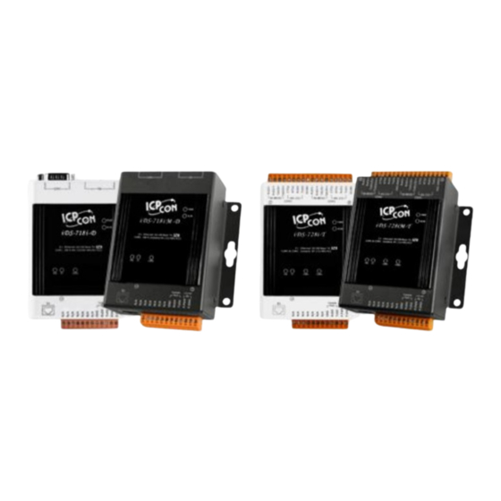
Intelligent Device Server with 1 RS-232/422/485 (Isolated, RoHS, DB9)
iDS-718iM-D CR
Intelligent Device Server with 1 RS-232/422/485 (Isolated, Metal Case, RoHS, DB9)
iDS-728i-T CR
Intelligent Device Server with 2 RS-232/422/485 (Isolated, RoHS, Terminal block)
iDS-728iM-T CR
Intelligent Device Server with 2 RS-232/422/485 (Isolated, Metal Case, RoHS, Terminal block)
iDS-448iM-D
Intelligent Device Server with 4 RS-232/422/485 (Isolated, RoHS, DB9)
Programmable Device Server User Manual (V1.1, Mar. 2020)
Programmable Device Server
User Manual
- 1 -
Advertisement
Table of Contents

Related Manuals for ICPDAS iDS-718i-D

Summary of Contents for ICPDAS iDS-718i-D
- Page 1 Non- Programmable Device Server User Manual iDS-718i-D Intelligent Device Server with 1 RS-232/422/485 (Isolated, RoHS, DB9) iDS-718iM-D CR Intelligent Device Server with 1 RS-232/422/485 (Isolated, Metal Case, RoHS, DB9) iDS-728i-T CR Intelligent Device Server with 2 RS-232/422/485 (Isolated, RoHS, Terminal block)
- Page 2 The names used for identification only may be registered trademarks of their respective companies. Contact US If you have any question, please feel free to contact us. We will give you quick response within 2 workdays. Email: service@icpdas.com , service.icpdas@gmail.com Programmable Device Server User Manual (V1.1, Mar. 2020) - 2 -...
-
Page 3: Table Of Contents
Table of Contents INTRODUCTION ------------------------------------------------------------------------------------------------------------- 5 1.1 P ACKING ------------------------------------------------------------------------------------------------------------------ 6 1.2 F EATURES ----------------------------------------------------------------------------------------------------------------------- 7 1.3 S PECIFICATIONS --------------------------------------------------------------------------------------------------------------- 8 1.4 O RDERING NFORMATION ----------------------------------------------------------------------------------------------------- 9 1.5 O PTION CCESSORIES --------------------------------------------------------------------------------------------------------- 9 GETTING STARTED -------------------------------------------------------------------------------------------------------- 10 2.1 D IMENSIONS AND OUNTING ----------------------------------------------------------------------------------------------- 10 2.2 P... - Page 4 4.3.1 TCP Server ----------------------------------------------------------------------------------------------------------- 35 4.3.2 TCP Client ------------------------------------------------------------------------------------------------------------ 36 4.3.3 -------------------------------------------------------------------------------------------------------------------- 37 4.4 P ONNECTION ----------------------------------------------------------------------------------------------------------- 38 4.4.1 Pair Connection Server -------------------------------------------------------------------------------------------- 38 4.4.2 Pair Connection Client --------------------------------------------------------------------------------------------- 39 4.5 RFC2217 -------------------------------------------------------------------------------------------------------------------- 40 4.6 E THERNET ODEM ----------------------------------------------------------------------------------------------------------- 41 Programmable Device Server User Manual (V1.1, Mar.
-
Page 5: Introduction
1. Introduction The iDS-700/400 Series is a new generation Device Server from ICP DAS and is equipped with a powerful CPU module running on the open operating system, various connectivity (Ethernet, micro SD and serial port) and communication interfaces. Compared with the previous generation PDS, not only the CPU performance is higher but also more features are improved such as 256 MB flash, 256 MB DDR3 memory, unique 64-bit hardware serial number, and real-time clock, etc. -
Page 6: Packing List
1.1 Packing List The package includes the following items: One (Programmable) Device Server hardware module One software utility CD One RS-232 console/download cable, CA-0903 One Quick Start Guide Note: If any of these items are missed or damaged, contact the local distributors for more information. -
Page 7: Features
Features Incorporate Serial Devices in an Ethernet network Virtual COM for 32-bit and 64-bit Windows XP/2003/Vista/7 High-performance ARM-based Processor 256 MB DDR3 memory for data transmission and buffering Zero Data Loss UDP Support RFC2217 support ... -
Page 8: Specifications
Specifications Models iDS-718i-D iDS-728i-T iDS-718iM-D iDS-728iM-T iDS-448iM-D CPU Module 32-bit High Performance Processor Peripheral microSD, RTC, 64-bit Serial Number, Watchdog, Buzzer Communication Interface COM1 5-wire RS-232/422/485 (Isolated) 8-wire RS-232/422/485 (Isolated) 5-wire 5-wire COM2 – RS-232/422/485 – RS-232/422/485 8-wire RS-232/422/485 (Isolated) -
Page 9: Ordering Information
5 ~ 90% RH, non-condensing Ordering Information Intelligent Device Server with 1 RS-232/422/485 (Isolated, RoHS, DB9) iDS-718i-D Intelligent Device Server with 1 RS-232/422/485 (Isolated, Metal Case, RoHS, DB9) iDS-718iM-D CR Intelligent Device Server with 2 RS-232/422/485 (Isolated, RoHS, Terminal block) -
Page 10: Getting Started
2. Getting Started 2.1 Dimensions and Mounting iDS Series Unit: mm Programmable Device Server User Manual (V1.1, Mar. 2020) - 10 -... - Page 11 Unit: mm Fig 2-3 Programmable Device Server User Manual (V1.1, Mar. 2020) - 11 -...
- Page 12 Programmable Device Server User Manual (V1.1, Mar. 2020) - 12 -...
- Page 13 Unit: mm Fig 2-4 Programmable Device Server User Manual (V1.1, Mar. 2020) - 13 -...
-
Page 14: Pin Assignment
Pin Assignment 2.2.1 iDS-718 Series E1 & CON1(1 ~ 12) Terminal NO Pin Assignment COM1 DIP Switch P.PWR CON1 (12~48V) P.GND Pull high/low resistors for the RS-422/RS-485 Port RS-485/RS-422 RS-485 RS-422 Switch Pull High/Low Terminator 1 KΩ 1 KΩ 120 Ω 120 Ω... - Page 15 COM1 Pin Assignment DIP Switch(COM1 Mode) RS232 RS422 RS485 COM1 DIP Switch TXD- Data- RS232 TXD+ Data+ RXD+ RS422 RXD- RS485 Software Programmable Device Server User Manual (V1.1, Mar. 2020) - 15 -...
-
Page 16: Ids-728 Series
2.2.2 iDS-728 Series CON2 E1 & CON1(1 ~ 12) Terminal NO Pin Assignment P.PWR (12V-48V) P.GND CON1 CON2(1 ~ 18) Terminal NO Pin Assignment RS-422_RxD2- RS-422_RxD2+ RS-422_TxD2/D2- RS-422_TxD2/D2+ COM2 RS-232_CTS2 RS-232_RTS2 RS-232_RxD2 RS-232_TxD2 GND2 RS-422_RxD1- RS-422_RxD1+ RS-422_TxD1/D1- RS-422_TxD1/D1+ COM1 RS-232_CTS1 RS-232_RTS1 RS-232_RxD1 RS-232_TxD1... -
Page 17: Ids-448 Series
2.2.3 iDS-448 Series E1, E2 & CON1(1 ~ 6) Terminal NO Pin Assignment E1、E2 P.PWR (12~48V) P.GND P.PWR COM3 COM4 P.GND COM2 COM1 Programmable Device Server User Manual (V1.1, Mar. 2020) - 17 -... -
Page 18: Led Indicators
COM1~4 Pin Assignment DIP Switch (COM1~4 Mode) RS232 RS422 RS485 COM1 DIP Switch TXD- Data- RS232 TXD+ Data+ RXD+ RS422 RXD- RS485 Software LED Indicators The iDS contains three LED indicators. LED In LED Indicators Color Meaning Power is on Green OS is running Ethernet... -
Page 19: Configuration Method
Factory Setting IP:192.168.255.1 NetMask:255.255.255.0 Gateway:192.168.255.254 Protocol : icpdas protocol 2.4.2 Setting IP Address Using web browser (IE or Chrome) and typing the default IP (192.168.255.1) to connect to the iDS devices to set IP address(DHCP or Static). Please refer to the Fig 2-4、2-5:... - Page 20 Set IP Information Click “Network“ Click “save” button to save the setting. Fig 2-6 Network Programmable Device Server User Manual (V1.1, Mar. 2020) - 20 -...
-
Page 21: Web Management Interface
3. Web Management Interface Web Browser User can use the web browser (IE 8 or later version, Chrome) to operate the iDS-700 series web management interface. User can input the IP address to connect to the “login” interface of iDS- 700 device. -
Page 22: Initialize Setting
3.2 Initialize Setting 3.2.1 Basic Setting Clicking the “Basic Setting” to set the iDS’s hostname or enable/disable the function “UDP search” (the system default don’t enable). Please refer to the Fig 3-2: Set the basic setting Click “Basic Setting” Click “Save” button to save the setting. -
Page 23: Network Setting
3.2.2 Network Setting Clicking the “Network” to set the IP address. Please refer to the Fig 3-3: Set IP Information Click “Network” Click “Save” button to save the setting. Fig 3-3 Network Programmable Device Server User Manual (V1.1, Mar. 2020) - 23 -... -
Page 24: Snmp
3.2.3 SNMP Clicking the “SNMP” to set the SNMP Agent. Please refer to the Fig 3-4: Set SNMP Configuration Click “SNMP” Click “Save” button to save the setting. Fig 3-4 SNMP Programmable Device Server User Manual (V1.1, Mar. 2020) - 24 -... -
Page 25: Account/Password Table
3.2.4 Account/Password Table Clicking the “Account/Password Table” to set the account information. Please refer to the Fig 3-5: Set account information Click “Save” button to save the setting. Click “Account/Password Table” Fig 3-5 Account/Password Table Programmable Device Server User Manual (V1.1, Mar. 2020) - 25 -... -
Page 26: Accessible Ip Table
3.2.5 Accessible IP Table Clicking the “Accessible IP Table” to enable/disable the rules of IP filter. Please refer to the Fig 3-6: Click “Edit” Click “Accessible IP Table Enable/Disable IP filer Save or Cancel the rules Fig 3-6 Accessible IP Table Programmable Device Server User Manual (V1.1, Mar. -
Page 27: Monitor
3.2.6 Monitor Clicking the “Line/Async/Async Setting” to get the COM’s information. Please refer to the Fig 3-7 and Fig 3-8: Get COM’s information Click “Async” Fig 3-7 Async Get COM’s information Click “Async Setting” Fig 3-8 Async Setting Programmable Device Server User Manual (V1.1, Mar. 2020) - 27 -... -
Page 28: Event Notification
3.2.7 Event Notification Clicking the “Events” and “Email/SNMP Trap” to set the function of events notification and inform the system administrator. Please refer to the Fig 3-9, Fig 3-10: Set the method of notification Click “Events” Click “Save” button to save the setting. -
Page 29: Firmware Upgrade
3.2.8 Firmware Upgrade Clicking the “Firmware upgrade” to update the iDS’s firmware. Please refer to the Fig 3-11: Please choose the icpdas’s firmware package. Click “Upload” button to upload the icpdas’s firmware package. Click “Firmware upgrade” Fig 3-11 Firmware upgrade 3.2.9... -
Page 30: Serial Port Operation Modes
4. Serial Port Operation Modes Serial Port Basic Setting Clicking the SERIAL PORT SETTING “Port1” to set the serial port’s basic configuration or click the SERIAL PORT SETTING “Advanced Options” to set the serial port’s modem control and command setting. Please refer to the Fig 4-1, Fig 4-2: Set Port’s Configuration Click “Port1”... - Page 31 Set Port’s Advanced Options Click Port1’s Advanced Options Click “Save” button to save the setting. Fig 4-2 Port1’s Advanced Option Programmable Device Server User Manual (V1.1, Mar. 2020) - 31 -...
-
Page 32: Virtual Com
Please install VxComm Utility (v 2.12.07 or later version), the software can download from below web link: http://ftp.icpdas.com/pub/cd/8000cd/napdos/driver/vxcomm_driver/ 4.2.2 Network Setting Please refer to chapter “3.2.2” to set network environment of iDS modules. Programmable Device Server User Manual (V1.1, Mar. 2020) -
Page 33: Configuring Virtual Com Ports
4.2.3 Configuring Virtual COM Ports Please refer to below steps to set and use the virtual COM ports. 1. Double click the VxComm Utility shortcut on the desktop. 2. Click the “Add Server*s+” button to connect to the iDS-700, then user assign a COM Port number and click “OK”... - Page 34 4. Click “Tools” >> “Restart Driver”, and then click the “Restart Driver” button, please refer to Fig 4-5. Click “Tools” >> “Restart Driver” Click “Restart Driver” Button Fig 4-5 Programmable Device Server User Manual (V1.1, Mar. 2020) - 34 -...
-
Page 35: Socket Modes
Socket Modes 4.3.1 TCP Server To click “DEVICE SERVER” >> “Port1” to choose “TCP Server” mode, please refer to Fig 4-6. After user had saved the setting, user must reboot iDS modules (please refer to the chapter “3.2.9 restart”). Choose “TCP Server” Set “Server Options”... -
Page 36: Tcp Client
4.3.2 TCP Client To click “DEVICE SERVER” >> “Port1” to choose “TCP Client” mode, please refer to Fig 4-7. After user had saved the setting, user must reboot iDS modules(please refer to the chapter “3.2.9 restart”). Choose “TCP Server” Set iDS’s port number Set remote server’s IP and port number Click “Port1”... -
Page 37: Udp
4.3.3 To click “DEVICE SERVER” >> “Port1” to choose “UDP” mode, please refer to Fig 4-8. After user had saved the setting, user must reboot iDS modules(please refer to the chapter “3.2.9 restart”). Choose “UDP” Set iDS’s port number Set remote host’s IP and port number Click “Port1”... -
Page 38: Pair Connection
Pair Connection 4.4.1 Pair Connection Server To click “DEVICE SERVER” >> “Port1” to choose “Pair Connection” mode, please refer to Fig 4-9. After user had saved the setting, user must reboot iDS modules(please refer to the chapter “3.2.9 restart”). Choose “Pair Connection” Choose “Server”... -
Page 39: Pair Connection Client
4.4.2 Pair Connection Client To click “DEVICE SERVER” >> “Port1” to choose “Pair Connection” mode, please refer to Fig 4-10. After user had saved the setting, user must reboot iDS modules(please refer to the chapter “3.2.9 restart”). Choose “Pair Connection” Choose “Client”... -
Page 40: Rfc2217
RFC2217 To click “DEVICE SERVER” >> “Port1” to choose “RFC-2217” mode, please refer to Fig 4-10. After user had saved the setting, user must reboot iDS modules(please refer to the chapter “3.2.9 restart”). Choose “RFC-2217” Set iDS’s port number Click “Save” button to save the setting. -
Page 41: Ethernet Modem
4.6 Ethernet Modem To click “DEVICE SERVER” >> “Port1” to choose “Ethernet Modem” mode, please refer to Fig 4-11. After user had saved the setting, user must reboot iDS modules(please refer to the chapter “3.2.9 restart”). Choose “Ethernet Modem” Set iDS’s Dial-in port number Set iDS’s Dial-Out port number Click “Save”...
Need help?
Do you have a question about the iDS-718i-D and is the answer not in the manual?
Questions and answers