
Related Manuals for Nidek Medical MC-500

Summary of Contents for Nidek Medical MC-500
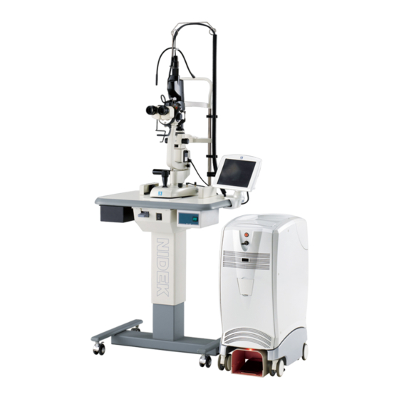
- Page 1 Multicolor Laser Photocoagulator Multicolor Laser Photocoagulator MC-500 MC-500 OPERATOR’S MANUAL OPERATOR’S MANUAL...
- Page 2 Original instructions NIDEK CO., LTD. : 34-14, Maehama, Hiroishi-cho, Gamagori, Aichi 443-0038, Japan (Manufacturer) Telephone: +81-533-67-6611 Facsimile: +81-533-67-6610 NIDEK CO., LTD. : 3F Sumitomo Fudosan Hongo Bldg., 3-22-5, Hongo, (Tokyo Office) Bunkyo-Ku, Tokyo 113-0033, Japan Telephone: +81-3-5844-2641 Facsimile: +81-3-5844-2642 NIDEK INCORPORATED : 47651 Westinghouse Drive, Fremont, California 94539, U.
- Page 3 APPLIED DELIVERY UNIT. This Operator’s Manual contains information necessary for the operation of the NIDEK Multicolor Laser Photocoagulator MC-500. This manual includes the operating procedures, safety precautions, and specifications. Especially, the cautions for safety and operating procedures must be thoroughly understood before using the device.
-
Page 5: Table Of Contents
Table of Contents 1. BEFORE USE ........1 1.1 Device Outline . - Page 6 3.7.4.2 Set Data Input/Output screen........47 { Printer setting ..........48 { LAN setting .
- Page 7 7.2 Management ............86 7.3 Function Check .
-
Page 9: Before Use
The NIDEK Multicolor Laser Photocoagulator MC-500 is a laser photocoagulator for ophthalmology with the light source of wavelengths 647, 577, and 532 nm. As the conventional laser photocoagulators, the MC-500 can be used for retinal photocoagulation for treatment of ocular fundus diseases like diabetic retinopathy, age-related macular degeneration, retin- opathy of prematurity, and retinal detachment, or for laser iridotomy and laser trabeculoplasty for treat- ment of glaucoma. -
Page 10: Principles
The MC-500 splits the pumped laser beam into the aiming and treatment beams to control them sepa- rately. Then the aiming and treatment beams are combined and lead to the fiber optic cable. The out- put end of the fiber optic cable is connected to the delivery unit. -
Page 11: Classifications
Form of protection method against electric shock: Class I The MC-500 is classified as a Class I device in which protection against electric shock and does not rely on basic insulation only, but which includes additional safety grounding of accessible conductive parts in the fixed wiring in such a way that accessible conductive parts cannot become live in the event of a failure of the basic insulation. -
Page 12: Symbol Information
BEFORE USE Symbol Information Symbol Information Indicates that the degree of protection against electric shock is of a Type B Applied Part. Indicates that when the switch is pressed to this symbol side, power is not supplied to the device. Indicates that when the switch is pressed to this symbol side, power is supplied to the device. -
Page 13: Precautions In Patient Selection
Patients with myopic choroidal neovascularization Patients with acute attack of primary angle closure (with corneal edema) Patients with late glauocoma or extremely high intraocular pressure Contraindications Use of the MC-500 is contraindicated in patients with foveal choroidal neovascularization or myopic choroidal neovascularization. -
Page 14: Adverse Events And Adverse Device Effects
BEFORE USE Adverse Events and Adverse Device Effects Adverse Events and Adverse Device Effects Potential adverse events accompanying the use of the MC-500 may include, but are not limited to the following: [Adverse events] • Increased intraocular pressure • Vitreous hemorrhage •... -
Page 15: Safety Precautions
SAFETY PRECAUTIONS In this manual, signal words are used to designate the degree or level of safety alerting. The defi- nitions are as follows. • Indicates a potentially hazardous situation which, if not avoided, may result in minor or CAUTION moderate injury or property damage accident. - Page 16 • The International Electrotechnical Commission sets the essential requirements for electrical and electronic equipment that may disturb, or be disturbed by, other equipment. The MC-500 complies with these requirements as shown in the tables "10 EMC (Page 103)" . Follow the guidance in the tables for use of the device...
-
Page 17: Handling Power Cord And Cables
SAFETY PRECAUTIONS Handling Power Cord and cables Handling Power Cord and cables • Follow the instructions below to handle the power cord and cables of the CAUTION photocoagulation system: - To avoid failure or malfunction, connect the cord and cable to the specified connec- tors securely. -
Page 18: Use
Contact coagulation by an electrosurgical knife may cause electric shock or burning. - The MC-500 main body is intended to be used in combination with the NIDEK SL- 1800, or Carl Zeiss Meditec 30SL/M or SL 130. Never use it singularly or in combi- nation with other medical devices. - Page 19 SAFETY PRECAUTIONS Use • Follow the instructions below before starting the photocoagulation system: WARNING - Make sure that there is no flammable anesthetic gas in the operating room prior to starting the photocoagulation system to prevent ignition or explosion caused by treatment beam emission.
- Page 20 • Follow the instructions below to emit the laser beam: - When the treatment beam (wavelength: 532, 577, and 647 nm) of the MC-500 is emitted to tissue, the following symptoms may occur. Pay attention to the direction of the aiming beam to avoid emission of the treatment beam onto eyes or skin inad- vertently.
- Page 21 SAFETY PRECAUTIONS Use - Perform the procedure below to confirm that the photocoagulation system is in a CAUTION proper condition for treatment beam emission. (If any abnormality is found in Step 2., ask NIDEK for check and maintenance.) 1. Project the aiming spot on a surface that is not specular. 2.
-
Page 22: Patient Environment
SAFETY PRECAUTIONS Patient environment Patient environment The patient environment is the volume of space in which contact can occur CAUTION between the patient and any part of the system or between the patient and any other person(s) touching the system. If a person handling a conductive part of the system comes into contact with a patient at the same time, hazard may occur due to leakage current exceeding the value specified in the applicable standard. -
Page 23: After Use, Maintenance, And Checks
SAFETY PRECAUTIONS After Use, Maintenance, and Checks After Use, Maintenance, and Checks • Follow the instructions below for after use of the photocoagulation system: WARNING - When the photocoagulation system is not being used, turn it OFF and put the dust cover over it to maintain the performance of laser beam emission. -
Page 24: Disposal
SAFETY PRECAUTIONS Disposal Disposal • When disposing the main body, ask NIDEK or your authorized distributor. CAUTION Inappropriate disposal may contaminate the environment. • Follow local governing ordinances and recycling plans regarding disposal or recycling of device components when disposing the foot switch or the delivery unit. Inappropriate disposal may contaminate the environment. -
Page 25: Safety Devices
Safety Devices [Key switch] For safety, only the designated key allows operation of the MC-500 so that only authorized person may use the system. The key cannot be removed when it is in the ON ( ) position. When the system is not in use, remove and store the key in a secure place. - Page 26 SAFETY PRECAUTIONS Safety Devices [Protective filter] To protect the physician’s eyes from any kind of hazardous radiation reflected from target tissue during the treatment beam emission, each delivery unit has a protective filter. If this filter is not set in the observation path, the treatment beam cannot be emitted even by pressing the foot switch.
-
Page 27: Labels
SAFETY PRECAUTIONS Labels Labels Cautionary labels are provided on the main body. [Rear view] For France "2.2 Handling Power Cord and cables (Page 9)". For France "2.2 Handling Power Cord and cables (Page 9)". - Page 28 SAFETY PRECAUTIONS Labels...
-
Page 29: Device Configuration
DEVICE CONFIGURATION Main Body - Front View Front delivery unit connectors (Optional) - Page 30 DEVICE CONFIGURATION Main Body - Front View LCD controller Attached to the motorized optical table and used to set and display the laser emission conditions. Emergency Off button Used to stop the photocoagulation system in case of emergency. When this button is pressed, power to the entire system is turned off, and all operations of the system stop.
-
Page 31: Main Body - Rear View (With Rear Cover Closed)
DEVICE CONFIGURATION Main Body - Rear View (with rear cover closed) Main Body - Rear View (with rear cover closed) - Page 32 DEVICE CONFIGURATION Main Body - Rear View (with rear cover closed) Connector access cover button Pressed to open the connector access cover. Light receptor Receives signals from the remote control (optional). Rear cover button Used to open the rear cover. “PUSH” is inscribed on the cover button. Pilot lamp Indicates the power status of the system.
-
Page 33: Main Body - Rear View (With Rear Cover Open)
DEVICE CONFIGURATION Main Body - Rear View (with rear cover open) Main Body - Rear View (with rear cover open) - Page 34 DEVICE CONFIGURATION Main Body - Rear View (with rear cover open) Fiber optic cable connector The fiber optic cable plug of the delivery unit is connected here. The CH1 “FIBER 1” is for the slit lamp or combination delivery unit, and the CH2 “FIBER 2” is for the Binocular Indirect Ophthalmoscope (hereafter called BIO) delivery unit.
-
Page 35: Lcd Controller (Main Screen)
DEVICE CONFIGURATION LCD Controller (Main Screen) LCD Controller (Main Screen) 3.4.1 For slit lamp or binocular indirect ophthalmoscope delivery unit COUNTER RESET button Pressing this button returns the counter to “0” (zero). The number of the treatment laser beam emission is displayed to the right of this button in the range of 0 to 9999. - Page 36 DEVICE CONFIGURATION LCD Controller (Main Screen) EMISSION indicator Indicated while the key switch is turned ON ( ). While the treatment beam is emitted, the EMISSION indicator appears in the color of the treatment beam being emitted. SPOT SIZE display Shows the diameter of the treatment beam spot (unit - μm) in the range from 50 to 1000 μm.
- Page 37 DEVICE CONFIGURATION LCD Controller (Main Screen) Function display Displays the function assigned to the Function button. For details of the assignable functions, see “3.7.3 Select Function screen (Page 42)”. Function button Used to execute the function assigned to the Function button. POWER display and buttons Shows the power output of the treatment beam (on the cornea) (unit - mW).
-
Page 38: For Scan Delivery Unit
DEVICE CONFIGURATION LCD Controller (Main Screen) 3.4.2 For scan delivery unit COUNTER RESET button Pressing this button returns the counter to “0” (zero). The number of the treatment laser beam emission is displayed to the right of this button in the range of 0 to 9999. - Page 39 DEVICE CONFIGURATION LCD Controller (Main Screen) EMISSION indicator Indicated while the key switch is turned ON ( ). While the treatment beam is emitted, the EMISSION indicator appears in the color of the treatment beam being emitted. SPOT SIZE display Shows the diameter of the treatment beam (unit - μm) spot in the range from 50 to 500 μm.
- Page 40 DEVICE CONFIGURATION LCD Controller (Main Screen) AUTO M. mode or when using Single scan pattern The interval time can be set between 0.3 and 1.0 second. SCAN mode The INTERVAL button is not displayed. Single mode The interval time can be set between 0.05 and 1.0 second. CUSTOM button Used to display the Custom screen to change parameters such as function settings or memory.
- Page 41 DEVICE CONFIGURATION LCD Controller (Main Screen) Scan pattern • The setting range of the scan pattern may differ depending on the combination of the scan pattern, spot size, spacing, and radius. • When the setting range of the scan pattern is changed by selecting another scan pattern, the settings such as the spacing may automatically be changed.
- Page 42 DEVICE CONFIGURATION LCD Controller (Main Screen) AIMING display and buttons Shows the intensity of the aiming beam. There is no indication when the aiming beam is off. AIMING buttons The intensity of the aiming beam can be set in 15 levels. The maximum level is 15. Each time the upper button is pressed, the aiming beam becomes more intense.
-
Page 43: Control Box (Optional)
DEVICE CONFIGURATION Control Box (optional) Control Box (optional) STATUS indication and button The treatment beam can be toggled between STANDBY and READY modes by pressing the STATUS button. When the treatment beam will not be emitted, set the system in STANDBY mode for safety. EMISSION indicator Indicated while the key switch is turned ON ( ). - Page 44 DEVICE CONFIGURATION Control Box (optional) INTERVAL display and buttons Shows the interval time in Repeat mode (unit - second). In Single mode, there is no indication. INTERVAL buttons Used to toggle between the Single and Repeat modes and set the interval time in Repeat mode (unit: second). Each time the upper button is pressed, the interval time becomes longer as “no indication (Single mode)”...
-
Page 45: Remote Control (Optional)
DEVICE CONFIGURATION Remote Control (optional) Remote Control (optional) COLOR button Used to select the color of the treatment beam. Each time this button is pressed, the color changes as “GREEN” o “YELLOW” o “RED”... The power setting is not changed when the color is changed. However, a power larger than the maximum value for each color (GREEN 1,700 mW, YELLOW 1,500 mW, RED 800 mW) cannot be set. - Page 46 DEVICE CONFIGURATION Remote Control (optional) INTERVAL buttons Used to toggle between the Single and Repeat modes and set the interval time in Repeat mode (unit: second). Each time the upper button is pressed, the interval time becomes longer as “no indication (Single mode)” o “0.05” o “0.10”...”1.0.” Each time the lower button is pressed, the interval time becomes shorter and finally the interval time indication disappears (Single mode).
-
Page 47: Custom Screen
DEVICE CONFIGURATION CUSTOM Screen CUSTOM Screen The CUSTOM screen is displayed by pressing the CUSTOM button in the Main screen. LCD Brightness Sound Volume Select Function Sw Other Memory List Modify Memory Data Exit LCD Brightness button Used to display the LCD Brightness Setting screen. For details, see “3.7.1 LCD Brightness screen (Page 40)”. -
Page 48: Lcd Brightness Screen
DEVICE CONFIGURATION CUSTOM Screen 3.7.1 LCD Brightness screen In this screen, the brightness of the LCD controller in STANDBY and READY modes can be set. LCD Brightness at Standby LCD Brightness at Ready Exit LCD Brightness at Standby The brightness of the LCD controller in STANDBY mode can be adjusted by pressing the buttons. -
Page 49: Sound Volume Screen
DEVICE CONFIGURATION CUSTOM Screen 3.7.2 Sound Volume screen In this screen, the volume of various sounds produced by the device can be set. Beep Console Beep Volume : Coag Speaker Volume Exit Beep Volume : Button The volume of the sound produced when the buttons on the control box are pressed can be adjusted by pressing the buttons. -
Page 50: Select Function Screen
DEVICE CONFIGURATION CUSTOM Screen 3.7.3 Select Function screen This screen allows the operator to assign the desired function to the Function button. Select Function Memory List LCD Brightness Sound Volume Other Modify Memory Data Interval On/Off Aming Power On/Off Exit 1. -
Page 51: Other Setting Screen
DEVICE CONFIGURATION CUSTOM Screen 3.7.4 Other Setting screen Other Setting Select Summary Display Set Data Input/Output Select Display Language Select Voice Language Set Clock Exit 1. Select Summary Display Used to display the Select Summary Display screen. For details, see “3.7.4.1 Select Summary Display screen (Page 44)”. -
Page 52: 3.7.4.1 Select Summary Display Screen
DEVICE CONFIGURATION CUSTOM Screen 3.7.4.1 Select Summary Display screen This screen allows the operator to set the condition to display the summary of treatment*. (* See the next page for details of the summary treatment.) Select Summary Display Not Display Change to STANDBY COUNTER Reset Exit... - Page 53 DEVICE CONFIGURATION CUSTOM Screen The summary of treatment shows various information on the laser emission that has been executed as shown below. <Summary of treatment screen> STATUS STANDBY Summary of treatment OUTPUT LEFT RIGHT SPOT SIZE μm COUNTER COLOR Setting POWER (mW) 0000 0000 Ave.
- Page 54 DEVICE CONFIGURATION CUSTOM Screen RIGHT button Used when the treatment data is for the right eye. For the treatment data for both eyes, the LEFT button can be pressed at the same time. This button is displayed when “LAN” is selected for the “Set Data Output” parameter in the Set Data Input/ Output screen.
-
Page 55: 3.7.4.2 Set Data Input/Output Screen
DEVICE CONFIGURATION CUSTOM Screen 3.7.4.2 Set Data Input/Output screen Set Data Input This screen allows the operator to toggle between the barcode reader or the card reader. Patient IDs read with the barcode reader or the card reader can be displayed in the message display of the LCD controller. -
Page 56: Printer Setting
DEVICE CONFIGURATION CUSTOM Screen Setting for outputting data { Printer setting 1) Press the Printer button. { LAN setting • NIDEK service personnel will perform the connection and setting with permission from a network administrator of each facility. • Before connecting the main body to the network, confirm the following points with the network administrator of the facility: 1. - Page 57 DEVICE CONFIGURATION CUSTOM Screen 4) Press the buttons in the screen and input the parameters. The password is displayed with ques- tion marks (?). Pressing the user name or the folder name button displays a keyboard. Input alphabetical characters. 5) Pressing the IP address or the sub- net mask button displays a numeri- keypad.
-
Page 58: 3.7.4.3 Select Display Language Screen
DEVICE CONFIGURATION CUSTOM Screen 3.7.4.3 Select Display Language screen This screen allows the operator to select the desired display language. Press to highlight the button shown to the left of the desired display language. Select Display Language English Japanese Exit Return button Used to return to the initial CUSTOM screen. -
Page 59: 3.7.4.4 Select Voice Language Screen
DEVICE CONFIGURATION CUSTOM Screen 3.7.4.4 Select Voice Language screen This screen allows the operator to select the desired voice guidance language. Press to highlight the button shown to the left of the desired voice guidance language. Select Voice Language English Japanese Exit Return button... -
Page 60: 3.7.4.5 Adjust Clock Screen
DEVICE CONFIGURATION CUSTOM Screen 3.7.4.5 Adjust Clock screen This screen allows the operator to set the clock and toggle display of the clock in the Main screen. Adjust Clock Push the button and input number 2009 Select display the clock on the main display. Exit Push the button and input number The three buttons in the upper row represent year, month, and day from the left to right. -
Page 61: Memory List Screen
DEVICE CONFIGURATION CUSTOM Screen 3.7.5 Memory List screen This screen allows the operator to view and call up the desired treatment beam setting data stored in the device. Memory No. Name Color Power Time Interval ABCDEFGHIJ 0.100 0.10 KLMNOPQRSTU 0.150 0.15 VWXYZabcdef 0.200... -
Page 62: Modify Memory Data Screen
DEVICE CONFIGURATION CUSTOM Screen 3.7.6 Modify Memory Data screen This screen allows the operator to save or modify the treatment beam setting data. Memory No. Name Color Power Time Interval 0.100 0.10 ABCDEFGHIJ 0.150 0.15 KLMNOPQRST 0.200 0.20 UVWXYZabcd 0.200 0.25 efghijklmn 0.300... - Page 63 DEVICE CONFIGURATION CUSTOM Screen Next button Used to display the screen below in which scan patterns can be saved or deleted. Pre button Used to display the screen in which treatment data Memory No. Pattern Space can be saved or changed. Scan Mode Single 1.00...
-
Page 64: Connecting Optional Accessories
DEVICE CONFIGURATION Connecting Optional Accessories Connecting Optional Accessories The MC-500 can output data to the NIDEK NAVIS software as an external device. • Before connecting cables, be sure to turn off power to the devices to be connected CAUTION with the cables. -
Page 65: Connecting Barcode Reader / Magnetic Card Reader
DEVICE CONFIGURATION Connecting Optional Accessories Connect the LAN cable to the network (hub) to which the computer is connected. LAN cable Computer • Be sure to connect the main body with a PC through a network hub. Never connect the main body directly to a PC. A connection failure may occur. Set the necessary parameters. - Page 66 DEVICE CONFIGURATION Connecting Optional Accessories Press the rear cover button to open the rear cover. Connect the USB connector of the barcode reader / magnetic card reader to the USB-A connector on the back of the main body. Then close the rear cover. USB-A Magnetic card reader Ferrite core...
-
Page 67: Reading Patient Id
DEVICE CONFIGURATION Reading Patient ID Reading Patient ID Patient IDs can be read using barcodes or magnetic cards. Patient IDs read from them are used in the NIDEK NAVIS software. • Although patient IDs can be read post- or preoperatively, be sure to read the patient ID before transferring the summary of treatment. - Page 68 DEVICE CONFIGURATION Reading Patient ID Read with the magnetic card reader. 1) Slide the card through the magnetic Card card reader. A beep sounds and the green LED turns off. When reading of the card is finished, the green LED illuminates again.
-
Page 69: 3.10 Foot Switch
DEVICE CONFIGURATION Foot Switch Postoperatively, press the COUNTER RESET button or the STANDBY button in the LCD controller to transfer the patient ID and the summary of treatment. (For details of button setting, see “3.7.4.1 Select Summary Display screen (Page 44)” When data transfer is complete, a message appears. - Page 70 DEVICE CONFIGURATION Foot Switch...
-
Page 71: Photocoagulation
1968, and the laser photocoagulation has been applied to various patholo- gies. The MC-500 is the instrument that the wavelength can be selected for laser photocoagulation in ophthalmol- ogy: red (wavelength: 647 nm), yellow (wavelength: 577 nm), and green (wavelength: 532 nm). Laser pho- tocoagulation by using the MC-500 can be applied to treat the following pathologies: •Diabetic retinopathy... -
Page 72: Characteristics Of Wavelength
PHOTOCOAGULATION Cautions in Ophthalmology 4.1.2 Characteristics of wavelength (a) Red wavelength • Highly absorbed by melanin in retinal pigment epithelium or choroid. • Lowly absorbed by hemoglobin. Laser beam is rarely scattered in intraocular transit. • Negligibly absorbed by xanthophyll in macula. This minimizes undesired inner retinal damage during macular photocoagulation. -
Page 73: Cautions In Photocoagulation
PHOTOCOAGULATION Cautions in Ophthalmology If the procedures in photocoagulation are improper, desired effect can not be obtained or it may dam- age the tissue. This occurs when the tissue to be treated can not be observed clearly. Corneal opaci- ties, opaque ocular media, vitreous hemorrhage can interfere with the laser surgeon’s view of appropriate target structures. -
Page 74: Contraindications For Photocoagulation
PHOTOCOAGULATION Cautions in Ophthalmology 4.2.2 Contraindications for photocoagulation The region which should not be photocoagulated and the reason are described below. 1. Fovea centralis Fovea centralis should not be photocoagulated by using any wavelength because it may cause a visual loss due to the degeneration of optic cell, or cause a formation of coincident scotoma at the photocoagulated tissue. -
Page 75: Treatment Parameters In Ophthalmology
PHOTOCOAGULATION Treatment Parameters in Ophthalmology Treatment Parameters in Ophthalmology Ophthalmic problems are effectively treated with red, yellow or green laser photocoagulation wave- lengths. Treatment parameters depend on a variety of factors including the type of tissue to be treated, the intensity of the lesion desired, and the individual pigmentation of tissue targets. Laser power should initially be set at a low level and then be increased gradually until the desired tissue effect is obtained. - Page 76 PHOTOCOAGULATION Photocoagulation by Optional Delivery Unit [References] Mainster, M: “Wavelength Selection in Macular Photocoagulation: tissue optics, thermal effects and laser systems” Ophthalmology, 93: 7, 952 - 958, 1986; L’ Esperance, FA: Ophthalmic Lasers, St. Louis, CV Mosby, 3rd ed, Volumes I and II, 1989; March, WF: Ophthalmic Lasers: a Second Generation, Thorofare (NJ): Slack, 1990;...
-
Page 77: Transport
TRANSPORT Be sure to perform the procedure below before transporting the photocoagulation system. Turn off power to the photocoagulation system. 1) Turn the key switch. 2) Turn ) the master switch of the main body, then confirm that the pilot lamp is not illuminated. - Page 78 TRANSPORT • Pay attention to the following points in handling of the fiber optic cable so that it is CAUTION not coiled with a radius of under 10 cm. 1. Do not coil the fiber optic cable with a radius of under 10 cm. 2.
- Page 79 TRANSPORT Remove the LCD controller from the main body. 1) Remove the partition. Partition 2) Disconnect the LCD controller plug from the MONITOR connector. Disconnect the scan delivery unit cable from the main body. 1) Remove the delivery unit cable plug from the SCAN connector.
- Page 80 TRANSPORT If necessary, remove the plug from the REMOTE connector. If any plug other than the short plug is connected, press the buttons on the sides of the plug and remove it. * If a remote cable is connected, remove, coil, and place it on a conve- Press nient place.
-
Page 81: Maintenance
MAINTENANCE List of Consumables Part name Part number Remarks 250 V 2.5 A Fuse 80402-02162 (5 mm in diameter 20 mm) Replacing Fuses If the pilot lamp does not illuminate when the master switch of the main body is turned ON ( even though the power cord is connected properly, fuses may be blown. - Page 82 MAINTENANCE Replacing Fuses Insert the tip of a flatblade screwdriver into the notch of the cover, then rotate the screw- driver to either side to open the cover.. Rotate the screwdriver to eihter side. Cover The cover opens. Remove the fuse holder and replace it with a new one. Fuse holder Pry out the fuse holder using a flatblade screwdriver.
- Page 83 MAINTENANCE Replacing Fuses The fuse rating is as indicated by the label on the main body. • Be sure to replace both of the two fuses with new ones of the same rating. CAUTION Otherwise, the performance of the photocoagulation system may be deteriorated, or system fail- ure or fire may result.
-
Page 84: Cleaning
MAINTENANCE Cleaning Cleaning 6.3.1 Cleaning the device exterior • Never use an organic solvent such as thinner, or abrasive cleaner. CAUTION The surfaces of the main body may become ruined or scratched. • Be sure to wipe the exterior of the main body softly. The surface of the main body may become scratched. -
Page 85: Calibrating Laser Power Output (Treatment And Aiming Beams)
MAINTENANCE Calibrating Laser Power Output (Treatment and Aiming Beams) Calibrating Laser Power Output (Treatment and Aiming Beams) 6.4.1 Measuring and calibrating laser power output (treatment beam) If the difference between the indicated and actual laser power outputs is greater than tolerance, laser power needs to be calibrated. - Page 86 MAINTENANCE Calibrating Laser Power Output (Treatment and Aiming Beams) Measure the minimum (50 mW), 200 mW, and the maximum power output of each color. 1) Set the laser emission conditions as follows: Emission time: 3.00 seconds Spot size: 500 μm (Slit lamp/attachable delivery unit) Single spot (Scan delivery unit) Working distance: 400 mW (Binocular indirect ophthalmoscope delivery unit) Laser power output: 50 mW, 200 mW, and maximum of each color...
- Page 87 MAINTENANCE Calibrating Laser Power Output (Treatment and Aiming Beams) 3) Input the password, then press the Etr button. Exit Change the offset and gain parameters for each laser color. Exit 1) Press the Power button. 2) Press the button of the parameter to be changed to indicate “ON”, then change the parameters using the up and down buttons.
- Page 88 MAINTENANCE Calibrating Laser Power Output (Treatment and Aiming Beams) 3) If the power differs between the CH 1 and 2, press the Aim P button and set the G Chan- nel 2, Y Channel 2, and R Channel 2 parameters. S Aim Offset S Aim Gain 10 Step...
-
Page 89: Measuring And Calibrating Laser Power Output (Aiming Beam)
MAINTENANCE Calibrating Laser Power Output (Treatment and Aiming Beams) 6.4.2 Measuring and calibrating laser power output (aiming beam) Orient the aperture of the delivery unit in a safe direction. Start the photocoagulation system. Prepare for power output measurement. 1) Turn off the aiming beam. 2) Project the aiming beam to the receiving surface of the detector, then adjust the aiming beam to an appropriate intensity with the AIMING buttons of the LCD controller or the control box (optional). - Page 90 MAINTENANCE Calibrating Laser Power Output (Treatment and Aiming Beams) Press the CALIBRATION button. Other Setting Select Summary Display Set Data Input/Output Select Display Language Select Voice Language Set Clock Exit 3) Input the password, then press the Etr button. Exit Change the offset and gain parameters for each laser color.
- Page 91 MAINTENANCE Calibrating Laser Power Output (Treatment and Aiming Beams) 1) Press the Aim P button. 2) Press the up and down buttons of the parameter to be changed to indicate “ON”, then change the parameters using the up and down buttons. •...
- Page 92 MAINTENANCE Calibrating Laser Power Output (Treatment and Aiming Beams)
-
Page 93: Administration And Checks
ADMINISTRATION AND CHECKS Administration and Controlled Area Cautions Appoint personnel to be in charge of storage and administration for the area in which the system is used. One qualified administrator and one sub-administrator are needed. Instruct the personnel who use the system to observe the following. -
Page 94: Management
ADMINISTRATION AND CHECKS Management Management (1) Qualified administrator and sub-administrator Post Name Signature • • • • • • • • • • • • • • • (2) Registration of the personnel who are allowed to use the system Post Name Signature... -
Page 95: Function Check
ADMINISTRATION AND CHECKS Function Check Function Check Be sure to check the items below before using the photocoagulation system. Record the results in the check list in “7.4 Check List” (page 90). Appearance Check the main body and accessories for any deformation or dirt (including on the mirror) which may interfere with the operation. - Page 96 ADMINISTRATION AND CHECKS Function Check TIME buttons Does the emission time correctly change in the determined increments with the operation of the TIME buttons? Does a beep sound at the time of the change? COLOR button Does the laser color change in the order of … o “RED” o “GREEN” o “YELLOW” o “RED” o …...
- Page 97 ADMINISTRATION AND CHECKS Function Check Foot switch Does the foot switch work properly? Is the treatment beam emitted by pressing the foot switch after the photocoagulation system is placed in READY mode by pressing the STA- TUS button? • Never direct the aperture of the delivery unit toward personnel or flammable CAUTION material since the laser beam is emitted.
-
Page 98: Check List
ADMINISTRATION AND CHECKS Check List Check List Date of check Check Item 1. Appearance 2. Power cord 3. Key switch 4. LCD controller 5. Control box 6. POWER buttons 7. TIME buttons 8. COLOR button 9. INTERVAL buttons 10. AIMING buttons 11. -
Page 99: Laser Beam Output Calibration List
ADMINISTRATION AND CHECKS Laser Beam Output Calibration List Laser Beam Output Calibration List Aiming beam Aiming beam Treatment beam Treatment beam Item Maximum output Minimum output Maximum output Minimum output Laser (mW) (mW) (mW) (mW) color Before After Before After After Before After... - Page 100 ADMINISTRATION AND CHECKS Laser Beam Output Calibration List...
-
Page 101: Troubleshooting Guide
TROUBLESHOOTING GUIDE Interlock and Error Numbers The MC-500 has the self-diagnostic function to check the system condition automatically. If any trou- ble occurs, the treatment beam will be blocked by the safety shutter, the power source for the laser is turned off and the EMISSION indication blinks, and the beep sounds are produced intermittently. -
Page 102: Error
TROUBLESHOOTING GUIDE: Interlock and Error Numbers 8.1.2 Error Error display Symptom Remedy Malfunction of photocoagulation Err 1 shutter Malfunction of electrically Err 2 powered protective filter Turn the key switch to the OFF position, Err 3 Malfunction of safety shutter then to the ON position again. - Page 103 TROUBLESHOOTING GUIDE: Interlock and Error Numbers Error display Symptom Remedy Protective filter signal circuit Err 55 failure Err 90 Program data failure Err 91 EEPROM data failure Err 93 Data failure Err 94 KEYLOCK error Err 95 CPU communication error Err 110 Laser malfunction (green) Abnormal current for driving the...
-
Page 104: Error Related To Lan
TROUBLESHOOTING GUIDE: Interlock and Error Numbers 8.1.3 Error related to LAN Error display Remedy LAN Write Error = 403, (0,0) DHCP Err. LAN Write Error = 405, (0,0) LAN Cable Connection Err. LAN Write Error = 451, (-220,c000005e) Turn the key switch to the OFF position, User Name Err. -
Page 105: Indications Of Misoperation
TROUBLESHOOTING GUIDE: Indications of Misoperation Indications of Misoperation The MC-500 produces a series of beeps to inform of misoperation. In such a case, a remedy is displayed in the LCD controller, and an abbreviated indication appears in the TIME display of the control box. - Page 106 TROUBLESHOOTING GUIDE: Indications of Misoperation...
-
Page 107: Specifications And Accessories
SPECIFICATIONS AND ACCESSORIES Specifications 1. Treatment beam • Type Laser-diode-pumped solid-state laser, and diode laser • Wavelength Green - 532 nm Yellow - 577 nm Red - 647 nm • Laser mode Continuous wave • Power output (on the cornea) 50 mW to maximum (Maximum power output - Green 1,700 mW, Yellow 1,500 mW, and RED 800 mW) (Maximum power output (with scan function) - Green 1,500 mW, Yellow 1,500 mW, and... - Page 108 SPECIFICATIONS AND ACCESSORIES: Specifications 4. Power supply • Voltage Single phase AC 230 V ±10% • Frequency 50/60 Hz • Power consumption 400 VA or less • Power cord 3.0 ±0.2 m long, 3P power cord with protective grounding terminal (UL hospital grade) 5.
-
Page 109: Standard Accessories
SPECIFICATIONS AND ACCESSORIES: Standard Accessories Standard Accessories •Main body 1 unit •Foot switch 1 unit •Power cord 1 unit •Other accessories 1 set LCD controller 1 unit Dust cover 1 unit Operator’s Manual 1 volume Key switch (including a spare) 2 units Power supply fuse (including two spares) 4 unit... -
Page 110: Optional Accessories
SPECIFICATIONS AND ACCESSORIES: Optional Accessories Optional Accessories •Control box •Beam splitter (for SL-1800, ZEISS SL 130, and ZEISS 30SL) •TV attachment (1/3 inch) •Co-observation unit •Head belt •Arm rest •Infrared remote control •Front delivery unit connectors •Laser goggles For red - Yamamoto Kogaku Co., Ltd., YL300 He-Ne For yellow and green - Yamamoto Kogaku Co., Ltd., YL-717 Nd-YAG SHG •Barcode reader •Card reader... -
Page 111: Emc
EMC (IEC 60601-1-2: 2001+A1: 2004) Guidance and manufacturer's declaration - electromagnetic emissions The MC-500 is intended for use in the electromagnetic environment specified below. The customer or the user of the MC-500 should assure that it is used in such an environment. - Page 112 Guidance and manufacturer's declaration - electromagnetic immunity The MC-500 is intended for use in the electromagnetic environment specified below. The customer or the user of the MC-500 should assure that it is used in such an environment. Immunity test IEC 60601 test level...
- Page 113 Guidance and manufacturer's declaration - electromagnetic immunity The MC-500 is intended for use in the electromagnetic environment specified below. The customer or the user of the MC-500 should assure that it is used in such an environment. Immunity test IEC 60601 test level...
- Page 114 RF communications equipment and the MC-500 The MC-500 is intended for use in an electromagnetic environment in which radiated RF disturbances are controlled. The customer or the user of the MC-500 can help prevent electromagnetic interference by maintaining a minimum distance between portable and mobile RF communications equipment (transmitters) and the MC-500 as recommended below, according to the maximum output power of the communications equipment.
-
Page 115: Glossary
GLOSSARY Aiming beam Laser beam that indicates the position to which the treatment beam is to be emitted Laser beam Aiming beam and treatment beam Main body Main body of the photocoagulation system Power output Power output of the treatment beam (on the cornea) (Unit: mW) Emission time Length of time that the treatment beam is emitted (Unit: second) Single mode/Repeat mode... - Page 116 GLOSSARY:...
Need help?
Do you have a question about the MC-500 and is the answer not in the manual?
Questions and answers
اللوحه الكهربائية الخاصه بالجهاز nidek mc 500 لا تعمل
If the electrical panel of the Nidek Medical MC-500 is not working, follow these troubleshooting steps:
1. Check if all digits on the control box display as “ ” when the master switch and key switch are turned ON.
- If not, contact NIDEK or an authorized distributor.
2. If the main screen is not displayed on the LCD controller, contact NIDEK or an authorized distributor.
3. For LAN-related errors, check the specific error message:
- DHCP error, LAN cable connection error, or PC name/LAN cable/PC error: check the cable and connections.
- User name, password/domain name errors: turn the key switch OFF, then ON again.
- If the issue persists, contact NIDEK or an authorized distributor.
This answer is automatically generated