
Subscribe to Our Youtube Channel
Related Manuals for Extech Instruments HDV7C-A4-60-1


Summary of Contents for Extech Instruments HDV7C-A4-60-1
- Page 1 User Manual Four-Way Articulating Probes Models HDV7C-A4–60–1 and –3. For use with HDV700 VideoScope.
- Page 2 Introduction Thank you for selecting the Extech four-way articulating camera probe. This probe is intended for use with the HDV700 VideoScope. The probe is manually controlled by its joystick, control buttons, and lock switch. The probe is also controlled by the HDV700 touch- screen for capturing camera images and video, image manipulation, and other functions as described in the HDV700 User Manual avail- able at the support site (see Support section).
-
Page 3: Probe Description
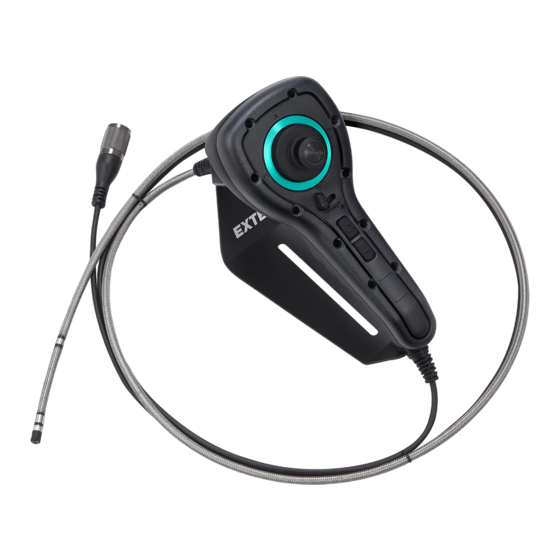
Probe Description 1. Joystick articulation control 2. HDV700 Connecting cable 3. Stabilizing stand 4. Hand grip 5. Image enhancement button 6. Camera probe 7. Articulation locking switch 8. Image rotation (90° clockwise) button 9. Image reflection filter button Connect the Probe Carefully connect the probe to the HDV700 as detailed below. -
Page 4: Probe Controls
Probe Controls Articulation Joystick Use the joystick (1) to move the probe neck in four directions as shown in the illustration below. The thumb is typically used to move the joystick while the hand grips the control unit. Set the control unit’s stabilizing base (3) on a firm platform for convenience. - Page 5 HDV700 Controls The HDV700 touch-screen offers additional functions and control of the probe such as recording images and video, split-screen views, image rotation, and more, as covered in the HDV700 user manual. Mirror Accessory The supplied mirror accessory provides a side view camera image. Use the HDV700 touch-screen to select forward and side camera views and to control the worklights (see HDV700 user manual).
-
Page 6: Measurement Considerations
Attach the accessory by rotating it clockwise onto the probe. Align the hole on the accessory to expose the worklight. Rotate the silver alignment sleeve to move left or right, as needed. Measurement Considerations • Ensure that the camera lens cap is removed before inserting the probe into the inspection area. -
Page 7: Two Year Warranty
Probe length 3.3 ft. (1 m) (HDV7C-A4–60–1) 9.8 ft. (3 m) (HDV7C-A4-60–3) Articulation Four–way articulation with 360° movement Probe head material Stainless steel Probe body material Stainless steel mesh Worklights LED lamps around camera lens and one side-view worklight for use with the supplied mirror accessory. - Page 8 #NAS100127; r. AB/87924/87926; en-US...
- Page 10 User Manual last page Website http://www.flir.com Customer support http://support.flir.com Copyright © 2022, FLIR Systems, Inc. All rights reserved worldwide. Disclaimer Specifications subject to change without further notice. Models and accessories subject to regional market considerations. License procedures may apply. Products described herein may be subject to US Export Regulations. Please refer to exportquestions@flir.com with any questions.
Need help?
Do you have a question about the HDV7C-A4-60-1 and is the answer not in the manual?
Questions and answers