Advertisement
Quick Links
Advertisement

Related Manuals for Geehy SEMICONDUCTOR APM32F407


Summary of Contents for Geehy SEMICONDUCTOR APM32F407
- Page 1 User Manual APM32F407 EVAL Board Version: V1.0...
- Page 2 Introduction This User Manual describes the functions, on-board resources and supporting SDK of APM32F407IG EVAL Board. The SDK and related data mentioned in the document can be obtained from the official website of Geehy (www.geehy. com). APM32 Ecosystem The APM32 ecosystem includes product application solution, hardware development board, download simulation tool, development tool chain and SDK.
- Page 3 Evaluation board APM32F407 EVAL Board is a complete demonstration and development platform for high-performance APM32F4xx series MCU, including a base board and two core boards. The two core boards use APM32F407ZGT6 (LQFP144) and APM32F407IG T6 (LQFP176) as the core master, and the two MCU chips are based on Arm ®...
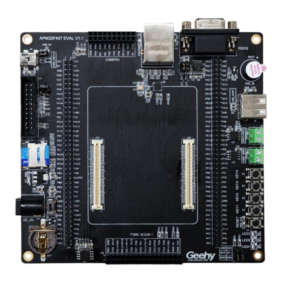
- Page 4 Figure 3 APM32F407ZG Core V1 Board Figure 4 APM32F407IG Core V1 board Figure 5 APM32F407 EVAL Board (taking APM32F407IG CoreV1 board as an example) 232 module USB module Ethernet Digital camera module module CAN module 485 module +5V power supply...
- Page 5 Contents Introduction ........................1 Function overview ......................5 SDK Overview ........................8 References ........................22 Revision History ......................23 www.geehy.com Page 4...
- Page 6 Function overview The APM32F407 EVAL Board mainly includes the following functional peripherals: 1. LDE:4 2. KEY:5 3. Buzzer: 1 4. JATA/SWD:1 5. Ethernet:1 6. USB-OTG:HS/FS 7. Support CAN-2.0/RS-232/RS-485 8. Support RTC with backup battery 9. Support MicroSD memory card 10. Support OV2640 camera module and expansion connector 11.
- Page 7 Power supply The APM32F407 EVAL Board can be powered by an external 5V DC power supply, or by selecting USB-to-serial port Mini USB interface through the jumper cap. Other required voltages are provided by the on-board voltage regulator. In addition, the JTAG interface can also supply power to the evaluation board, but it can only supply 3.3V voltage to the...
- Page 8 It supports 4.3-inch TFT color LCD touch screen with 800 x 480 pixels, and drives the LCD screen through the SMC and I2C interfaces of MCU. LED lights APM32F407 EVAL Board carries 3 user LED lights, which can be used for display by users or for indication purpose during the experiment. Keys APM32F407 EVAL Board carries 3 user keys, which can be used for LCD menu switching or other input purposes.
- Page 9 SDK Overview The SDK[1] is provided in the form of compressed packages, including on-board driver packages, such as basic LED, Button, Buzzer and COM driver, DCI OV2640 driver package, LCD screen driver package, SPI W25Q16 Flash driver package, SDIO SD Card driver package and so on.
- Page 10 On-board driver The on-board drivers include basic LED, Button, Buzzer and COM drivers, DCI OV2640 driver package, LCD screen driver package, and W25Q16 Flash driver package. Figure 9 On-board Driver Library file The library file contains APM32F4xx standard peripheral driver library, Ethernet peripheral driver library and USB OTG peripheral driver library.
- Page 11 Routine The SDK package contains many applications that are easy to reuse, such as DCI OV2640 camera, LCD touch screen, RS485 communication, CAN communication and Ethernet RS485. CAN LoopBack 3.5.1 The CAN LoopBack routine describes how to configure communication in loopback mode, and compares the received message with the transmitted message.
- Page 12 www.geehy.com Page 11...
- Page 13 DCI OV2640 3.5.3 DCI OV2640 routine shows how to obtain image data of OV2640 camera by using DCI. DCI continuously obtains the data of OV2640 camera through DMA and sends it to LCD through USART2. When KEY1 is pressed, select RGB565 data format; when KEY2 is pressed, select JPEG data format.
- Page 14 ETH Ping 3.5.5 This routine describes how to use APM32F4xx_ ETH_ Driver library to use Ethernet functions. After the Ethernet motherboard is configured, the static IP address from USART1 to printf will be used. If the computer pings the static IP address (192.168.73.22), the computer will access the motherboard normally.
- Page 15 ETH TCP Client 3.5.6 This routine describes how to use APM32F4xx_ ETH_ Driver library to use Ethernet function. After initialization, you can see the system information of the serial port assistant through the USART1 or LCD screen. Connect to the server (IP 192.168.73.51:6000). Disconnect the server through KEY2.
- Page 16 ETH TCP Server 3.5.7 This routine describes how to use APM32F4xx_ ETH_ Driver library to use Ethernet functions to create TCP server, receive and send data to TCP client through tcp assistant. After initialization, you can see the system information of the serial port assistant through the USART1 or LCD screen.
- Page 17 LCD ShowFigure 3.5.8 LCD_ShowFigure routine describes how to use the LCD driver to display graphics on the LCD screen. Press KEY1 and the LED will display different states. (LCD screen is 4.3 inches, 800 x 480 pixels). Figure 17LCD ShowFigure LCD Touch 3.5.9 LCD_Touch routine describes how to use interrupts to obtain LCD touch screen data.
- Page 18 3.5.10 RTC Alarm This routine describes how to use the RTC Alarm function. After initialization, LED2 will light up; count down for five seconds, then wake up the RTC alarm, LED2 will go out, and LED3 will flash. It can be monitored through USART1. 3.5.11 RTC Calendar This routine describes how to use the RTC calendar function.
- Page 19 3.5.12 SDIO SD Card This program shows how to use the SDIO module to access the SD card data through DMA and verify it after transmission. The data of the SD card can be displayed using the serial port assistant. After the power supply, single-block test or multiple-block test can be selected by KEY1 and KEY2.
- Page 20 3.5.13 SPI Flash This routine uses SPI interface to access the external flash chip W25Q16, with a size of 16M Bit. The test process is to press KEY1, write and read data to Flash and compare them. If the compared read and written data are equal, LED1 will light up and it can be monitored through USART1.
- Page 21 3.5.15 USART Polling This program is designed to show how to send or receive data by polling. In this case, USART1 and USART2 send or receive data from each other. Verify after transmission. If the data transmission from USART1 to USART2 is successful, LED2 will light up. If the data transmission from USART2 to USART1 is successful, ED3 will light up.
- Page 22 This routine implements virtual serial port device through the USB OTG peripheral of APM32F407, and the evaluation board is configured as the Device. When the USB port of the evaluation board is connected to the PC terminal, you can see an additional COM port in the device manager.
- Page 23 References For chip specifications and peripheral details, see APM32F4xxx User Manual, APM32F405xG 407xExG Data Manual, APM32F407ZG Core Schematic Diagram, and APM32F407IG Core Schematic Diagram. For more technical support, please visit the official website of Geehy: www.geehy.com. www.geehy.com Page 22...
- Page 24 Revision History Table 1 Document Revision History Date Revision Changes 2023.1.18 www.geehy.com Page 23...
- Page 25 Statement This manual is formulated and published by Zhuhai Geehy Semiconductor Co., Ltd. (hereinafter referred to as "Geehy"). The contents in this manual are protected by laws and regulations of trademark, copyright and software copyright. Geehy reserves the right to correct and modify this manual at any time.
- Page 26 (including without limitation data loss or inaccuracy, or losses suffered by users or third parties). 8. Scope of application The information in this manual replaces the information provided in all previous versions of the manual. ©2023 Zhuhai Geehy Semiconductor Co., Ltd. - All Rights Reserved www.geehy.com Page 25...
Need help?
Do you have a question about the APM32F407 and is the answer not in the manual?
Questions and answers