Table of Contents
Advertisement
Quick Links
Liquid Nitrogen Generator
Instruction Manual
EMP-14A
Export Control Policy
When applying a refrigerator to a cryocooler for optical sensors, the
cryocooler falls under row 6.A.2.d.2 of the control list established by
The Wassenaar Arrangement, which is equal to row 10(2) of
appended table 1 of Japan's Export Trade Control Order.
Customers must follow all related rules and regulations such as
Foreign Exchange and Foreign Trade Act and take appropriate
procedures when exporting or re-exporting our refrigerators.
D/N.MJOM116E, 2019OR04
ULVAC CRYOGENICS INCORPORATED
Advertisement
Table of Contents

Related Manuals for Ulvac EMP-14A


Summary of Contents for Ulvac EMP-14A
- Page 1 1 of Japan’s Export Trade Control Order. Customers must follow all related rules and regulations such as Foreign Exchange and Foreign Trade Act and take appropriate procedures when exporting or re-exporting our refrigerators. D/N.MJOM116E, 2019OR04 ULVAC CRYOGENICS INCORPORATED...
- Page 3 (1) It is strictly prohibited to duplicate or distribute this instruction manual or any of its parts to a third party without written permission from ULVAC CRYOGENICS. (2) Information in this document is subject to change without notice due to specification change or the improvement of the product.
- Page 4 There is a risk of fire or explosion. Hazardous voltage . Electric shock may cause severe injury or loss of life. Hot heating part present. There is a risk of burn injury. Low-temperature area present. There is a risk of frostbite. Do not touch. ULVAC CRYOGENICS INCORPORATED...
-
Page 5: Table Of Contents
Front view of EMP-14A (Figure 2-1) ············································ 7 Operation panel of EMP-14A (Figure 2-2) ····································· 7 Inside of EMP-14A front door and lower panel (Figure 2-3)············· 11 Inside the lower panel on the back ············································ 11 EMP-14A Electrical circuit(Figure 2-4) ··································· 12 EMP-14A Top side (Figure 2-5) ················································... - Page 6 Checks prior to operation ························································ 22 Prepare for operation ····························································· 22 Shutdown ············································································ 23 When resuming EMP-14A after suspending for 1 or 2 weeks ·········· 23 Corrective action in the event of an error ···································· 24 Emergency off ······································································ 25 Dispense Liquid Nitrogen Manually ··················································...
-
Page 7: Safety Instructions
The volume of nitrogen gas is 700 times of liquid nitrogen. Containing liquid nitrogen of atmospheric pressure in an airtight space makes it into high-pressure gas as high as 700atm, possibly resulting in explosion. Use liquid nitrogen in the condition constantly open to air. ULVAC CRYOGENICS INCORPORATED... - Page 8 (under regular maintenance, there is no need to discharge gas). In addition, never attempt to install the apparatus under the atmosphere of hydrochloric acid-based, chlorine gas-based, and other corrosive gases. ULVAC CRYOGENICS INCORPORATED...
-
Page 9: Disposal Considerations
When the refrigerator unit may have pumped toxic or dangerous gases, you must contact your safety supervisor at the time of disposal, and follow the instructions to remove hazardous substances before disposing. We provide Safety Data Sheet (SDS) of our products upon your request. Please contact us when necessary. ULVAC CRYOGENICS INCORPORATED... - Page 10 This page intentionally left blank. ULVAC CRYOGENICS INCORPORATED...
-
Page 11: General Description Of The System
(2) Membrane nitrogen generator. Liquid nitrogen generator is hereafter referred to as “EMP-14A” in this manual. Helium gas compressor (model:SA115-C) This unit is mounted in the lower part of EMP-14A, compress Helium gas and supply to the cold head to provide cryogenic temperatures. -
Page 12: Component Description
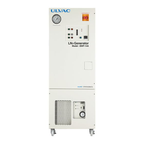
2. Component Description Emergency Off Button Pressure Gauge Operation Panel LN2 Manual Dispense Port SA115-C Display Air Entrance Figure 2-1 Front view of EMP-14A RUN/STOP RESET COMP.AL. OR 80 GN2 AL. 60 Maintenance AUTO AUTO 40 READY SUPPLY 20 0 Temperature L... -
Page 13: Front View Of Emp-14A (Figure 2-1)
Front view of EMP-14A (Figure 2-1) Emergency off button Press this button to interrupt power supply to the control circuit to stop such operations as dispensing liquid nitrogen. Do not use this button except for emergency. Front door Remove two screws to open this door. Inside the door, there are a liquid nitrogen dewar, a cold head and electric circuits. - Page 14 Lights red when the SA115-C encounters an error. The RUN/STOP button blinks at the same time. GN2 AL. The indicator lights red when the nitrogen gas generator stops due to faults. Then RUN/STOP switch blinks as well. ULVAC CRYOGENICS INCORPORATED...
- Page 15 Maintenance This light illuminates when the maintenance interval of GN-10i is approaching. Temperature meter Temperature meter is an optional. It displays the temperature inside the dewar. ULVAC CRYOGENICS INCORPORATED...
- Page 16 Electrical circuit 電気回路部 Operation ON/OFF switch OPERATIONスイッチ RUNNING TIME He PRESSUREMETER He GAS CHARGE Compressor コンプレッサー SA115-C SA115 Figure 2-3 Inside of EMP-14A front door and lower panel Automatic transfer port 自動供給配管継手 ヒューズ レベル計変換器 Level sensor converter Fuse シーケンサー 電源ブレーカー Circuit breaker 端子台 Terminal...
-
Page 17: Inside Of Emp-14A Front Door And Lower Panel (Figure 2-3)
Inside of EMP-14A front door and lower panel (Figure 2-3) Liquid nitrogen dewar Stores liquid nitrogen up to 40 liters. Cold head (S050) The cold head works in conjunction with SA115-C compressor to achieve ultra-low temperature. The cold head requires... -
Page 18: Emp-14A Electrical Circuit(Figure 2-4
EMP-14A Electrical circuit(Figure 2-4) Power breaker This is a protective breaker for control circuit of EMP-14A. It trips when an electric leak or short-circuit occurs. Fuse Protective fuses for AC circuit (F-1, 2: 3A) and protective fuses for DC circuit (F3: 2A). -
Page 19: Flow Diagram
3. Flow Diagram <Note> The configuration may differ depending on the customer specifications. Figure 3-1 Flow Diagram ULVAC CRYOGENICS INCORPORATED... -
Page 20: Specifications
(Non-condensation other than LN2 manual dispense port) EMP-14A is for indoor use only. As EMP-14A is air-cooled, make sure that the air intake and exhaust ports are always open, not blocked. PSA (Pressure Swing Adsorption) nitrogen gas generator... -
Page 21: Utilities
5. Utilities Power source (for EMP-14A) Voltage : 200VAC±10%, three-phase Power capacity : 20A or more Power consumption : 1.7/2.0 kW (50/60 Hz) Connection : Round type crimping terminal for M5 CAUTION Use D-type earth ground for safety. Power source (for the use with GN-10i) Voltage : 100VAC±10%, single-phase... -
Page 22: Installation
Top side 3 0 0 正面 Front ※ 背面以外のスペースは、保守点検時にのみ必要であり、 Spaces other than the back are required only 常時確保していただく必要はありません。 at the time of maintenance and check. Figure 6-1 Maintenance space for EMP-14A (4) Lock the wheels to fix the equipment. ULVAC CRYOGENICS INCORPORATED... -
Page 23: Connection Of Gn-10I To Power Source
IM-120. Utility connection of EMP-14A Remove the back panel of EMP-14A and locate holes for utility connection on the bottom. Connect cables through these holes including power-supply, Nitrogen tube and remote cables of Nitrogen generation system, signal cables for automatic transfer destination. - Page 24 (1) Use tools such as circuit tester to check that the supply voltage is within the appropriate range as described in “5. Utilities”. (2) Connect the crimping terminal side of power cables to EMP-14A through the holes on the bottom. Connect the cables that have matching marks on the terminal block (R, S, T, E).
- Page 25 6.4.2 Connecting nitrogen tube Connect the nitrogen gas tube to the nitrogen gas inlet connector located on the dewar of EMP-14A. Connect the opposite side of nitrogen gas tube to the nitrogen gas supply valve on the generator. 6.4.3 Connection of “Nitrogen gas generator” remote cable Connect a remote cable to the remote connector located inside of EMP-14A and the signal connector from the back of GN-10i , or “PRESSURE SWITCH OUT”...
-
Page 26: Electric Wiring
7. Electric Wiring Figure 7-1 Electric wiring-1 EMP-14A ULVAC CRYOGENICS INCORPORATED... - Page 27 Figure 7-2 EMP-14A Electric wiring-2 (Sequencer) ULVAC CRYOGENICS INCORPORATED...
-
Page 28: Operation
Check the following before starting the operation. (1) The power source of the EMP-14A and GN-10i is connected correctly. (2) The air inlet and outlet ports of EMP-14A and GN-10i are cleared. (3) The nitrogen gas tube is connected correctly between EMP-14A and the nitrogen generators. -
Page 29: Shutdown
In such a case, turn OFF the breakers of main power source and the electric circuit of EMP-14A, replace 2 cables out of 3 on the main power source, and turn on the power again. -
Page 30: Corrective Action In The Event Of An Error
Corrective action for COMP. AL. (1) Check the electric supply voltage and capacity. (2) Remove the acrylic panel of EMP-14A compressor display, turn down the lever of compressor OPERATION switch and return it to upward again. (3) Press RESET button of EMP-14A. -
Page 31: Emergency Off
Emergency off In case of an emergency, press the emergency off button on the front panel to disconnect the control power supply and stop all the operation of EMP-14A. CAUTION An emergency shutdown might damage the equipment. Do not use this button except in emergency. -
Page 32: Dispense Liquid Nitrogen Manually
Connecting liquid nitrogen flexible hose Connect the coupler joint of the flexible hose to LN manual dispense port on the front panel of EMP-14A. When connecting, do so while pushing down the outer ring part. Dispense liquid nitrogen To manually dispense liquid nitrogen, put the end of the flexible hose into the desired dewar, and press-and-hold MANU START button for 3 seconds. -
Page 33: Disconnecting Flexible Hoses
Note that disconnecting hoses right after dispensing liquid nitrogen may result in damaging the O-ring inside the coupler joint. Disconnect flexible hoses with the reverse procedure to connecting. Push down the outer ring of the EMP-14A side joint and pull out the flexible hose. ULVAC CRYOGENICS INCORPORATED... -
Page 34: Automatic Transfer Of Liquid Nitrogen
10.1 Inspections before starting automatic transfer Before starting automatic transfer, make sure of the following: (1) The level indicator cable is properly connected between EMP-14A and the level sensor of the target device. (2) Liquid nitrogen supply tube is properly connected between EMP-14A and the target dewar. -
Page 35: Eco Mode
11. eco Mode 11.1 mode The operation of EMP-14A will be turned to eco mode by pressing “eco” button on the operation panel. When in eco mode, EMP-14A is operated as follows. When EMP-14A does not receive any requests for LN2 production and transfer, EMP-0114A will be operated with the cycle of 22 hours’... -
Page 36: Maintenance And Inspections
IM-120 Check Valve Check the total operation time of EMP-14A with the hour meter on SA115-C. When the maintenance interval approaches, the Maintenance light blinks. *1… The coldhead should be replaced once every 10,000 hours of operation. -
Page 37: Regular Customer Inspection
12.3 Regular customer inspection The EMP-14A is a high pressure manufacturing equipment. Please follow the applicable laws or regulations when operating and maintaining this equipment. ULVAC CRYOGENICS INCORPORATED... -
Page 38: Troubleshooting
Suspend and resume EMP time. and GN-10i. IM-120 is suspended. Check the dry air supply pressure. Nitrogen gas supply Refer to “9-5-3. Corrective decreases, or the pressure is action when GN2 AL. occurs” lowered temporarily. and restart EMP 14A. ULVAC CRYOGENICS INCORPORATED... - Page 39 LN production Condensation occurs in the Check the connection (Alarm light is not lit). level sensor of EMP-14A. between EMP-14A and nitrogen generator, and flow rate of nitrogen gas. The level sensor needs to be dried. Please contact us.
- Page 40 Please contact us. such as helium. Ice or frost adheres to inside Please contact us. the dewar or around the cold head. The purity of Nitrogen gas is Check the purity of nitrogen not sufficient. gas supplied. ULVAC CRYOGENICS INCORPORATED...
- Page 41 Please contact us if any problem is found. (13) Other failures Please contact us. ULVAC CRYOGENICS INCORPORATED...
-
Page 42: Accessories
Instruction Manual IM-120 Remote Cable for Nitrogen Generator 1 (5m) Connector for Tubes 1 (Screw size: R1/4) Dry Air Supply Tube 1 (5m) Instruction Manual The above accessories may vary depending on the directions by customers. ULVAC CRYOGENICS INCORPORATED... -
Page 43: Warranty
As a general rule, diagnosis of failure should be done on site by customer. However, ULVAC CRYOGENICS or our service network can perform this service for an agreed fee upon the customer’s request. There will be no charge if the cause of the breakdown is found to be a fault of ULVAC CRYOGENICS. - Page 44 ULVAC CRYOGENICS products and other services are not covered under warranty. 3. Repair period after production is discontinued ULVAC CRYOGENICS shall accept product repairs for seven years after production of the product is discontinued. Manufacturer:...
- Page 45 ULVAC CRYOGENICS INC. www.ulvac-cryo.com 1222-1 Yabata, Chigasaki, Kanagawa 253-0085, Japan <Sales> Tel: +81-467-85-8884 <Service Engineering Division> Tel: +81-467-85-9366 Fax: +81-467-83-4838 ULVAC CRYOGENICS KOREA INC. www.ulvac-cryo.co.kr 107, Hyeongoksandan-ro, Cheongbuk-Myeon, Pyeongtaek-si, Gyeonggi-Do, Korea, 17812 Tel: +82-31-683-2926 Fax: +82-31-683-2956 ULVAC CRYOGENICS (NINGBO) INC.
- Page 46 This page intentionally left blank. CS-2 ULVAC CRYOGENICS INCORPORATED...
- Page 47 Company address has been changed. 2017 / 02 / 22 2017FY03 “Safety Instructions” has been changed. 2019OR04 2019 / 10 / 07 The model name of the compressor unit has been changed. The temperature indicator has been modified as optional. ULVAC CRYOGENICS INCORPORATED...
- Page 48 This page intentionally left blank ULVAC CRYOGENICS INCORPORATED...
Need help?
Do you have a question about the EMP-14A and is the answer not in the manual?
Questions and answers