
Related Manuals for Trox Qlci


Summary of Contents for Trox Qlci
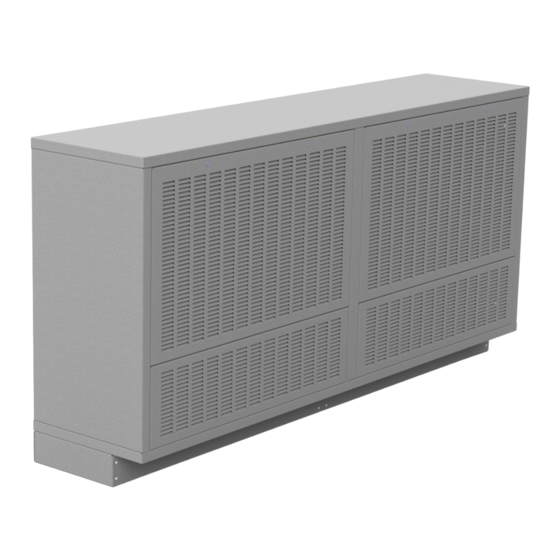
- Page 1 QLCI with REAR FIN TUBE HEATER ELEMENTS INSTALLATION, OPERATION, & MAINTENANCE (IOM) MANUAL v1.1 – Issue Date: 02/2023 © 2022 Carson Solutions. All rights reserved.
-
Page 2: Table Of Contents
2.4.2 Unit Weights Manufacturer’s Representations Installation 15-16 & Warranties General Procedure Installation Considerations Installing the QLCI with Rear Fin Tube Elements Water Connections 3.4.1 Water Connections Identification Condensate Drain Connection Air Connection Flushing the Water Piping System Filling and Venting the Water System 952.525.2050... -
Page 3: General Information
The integral hydronic coil within the unit is sized to allow the QLCI terminal to condition the room while the central system air handler supplies air at (or near) the mandated space ventilation rate. -
Page 4: Product Description And Installation Preparation
½ Sloped condensate trays with capped ” drain • space via a grill mounted on the lower face of the QLCI unit. In • Architectural cabinets certain circumstances designers have elected to apply optional rear fin tube heating elements for either primary or supplemental heating in the space. -
Page 5: Installation
Deviation from the designed plan should be avoided as the QLCI unit locations and configurations is critical to the comfort of the conditioned space. Units are designed for easy installation and access for maintenance. - Page 6 There may be plastic clips on the Fin Tube Elements from the manufacture, these can be discarded. STEP 2: Example install QLCI hydronic water piping a.) Typically, a BUC is used where the water pipes are dropped e.) Once all Fin Tube Elements are installed, begin joining all from the ceiling along a wall perpendicular to the exposure piping together (Straight pipe and fittings supplied by others).
- Page 7 Installation b.) Install threaded ½˝ NPT connections (provided by others) b.) Position the first QLCI unit (nearest the supply air duct) on each pipe or solder straight end connections 2˝ to 3˝ from against the wall. Secure units to the 2x4 Mounting Boards the point where the QLCI units connect to each other along ⅜”...
- Page 8 This Phillips head truss screws and (4) 5/16” Serrated nuts per allows the QLCI to be mounted to the 2x4’s first, then connect QLCI. End wall units only require 2 of each per QLCI. Locate the ductwork before making the piping connections.
-
Page 9: Water Connections
Installation 3.4 WATER CONNECTIONS 3.4.1 WATER CONNECTIONS IDENTIFICATION The QLCI unit is fitted with four water pipes which terminate in Piping connections for standard 2-pipe and 4-pipe QLCI ½” NPT threaded male connections. Each coil is factory tested displacement induction ventilation diffusers to be operated for leakage and provided clean and capped. -
Page 10: Air Connection
To ensure easy venting, the main pipes should be installed at a higher level than the QLCI units. The horizontal pipes should be The air connections should include a minimum of three duct installed rising slightly towards the venting points. -
Page 11: Commissioning
The total supply air flow (primary + induced) cannot be measured. NOTE: Using a traverse duct calculation of the supply duct before the QLCI will not guarantee that the diffuser is properly balanced because performance is based on internal plenum pressure. 952.525.2050 www.carsonsolutions.com... - Page 12 K = constant - read from Table below ΔP = static pressure measured in primary air chamber (in. W.G.) Example: Size 1500mm QLCI, 2R-nozzle measured static pressure of 0.295 in. W.G. K = 221 (from Table 2) CFM = 213 x √0.295 = 120.0 CFM...
-
Page 13: Maintenance
The inspection frequency is subject to the environmental conditions and occupancy levels. It is recommended that the QLCI units be inspected on an annual basis until a scheduled maintenance pattern is established. -
Page 14: Troubleshooting
Troubleshooting 6.1 SYMPTOMS & SOLUTIONS SYMPTOM PROBABLE CAUSE SOLUTION Obstruction on front face panel or Remove front face panel and inspect/clean grill hydronic coil and hydronic coil as necessary Inspect attachment hardware and Air connection detached from diffuser reconnect ductwork Remove primary air connection and LOSS OF AIRFLOW Obstruction in primary air plenum... -
Page 15: Manufacturer's Representations & Warranties
Warranties 7.1 MANUFACTURER’S REPRESENTATIONS & 6. CHANGES, CANCELLATION & RETURNS: Changes requested by Buyer following Seller’s acceptance of order must be approved by Seller in writing WARRANTIES and may result in an increase in price by Seller to recover all labor and material costs, including normal overhead and profit. - Page 16 Warranties 10. LIABILITY DISCLAIMER: TO THE MAXIMUM EXTENT PERMITTED BY LAW, SELLER’S TOTAL LIABILITY FOR CLAIMS, REGARDLESS OF THE FORM OF ACTION OR THEORY OF LIABILITY (INCLUDING CONTRACT, TORT OR WARRANTY), SHALL BE LIMITED TO THE FEES PAID TO SELLER BY BUYER FOR THE PRODUCTS OR LABOR THAT WAS THE PROXIMATE CAUSE OF THE DAMAGE.
Need help?
Do you have a question about the Qlci and is the answer not in the manual?
Questions and answers