Advertisement
Quick Links
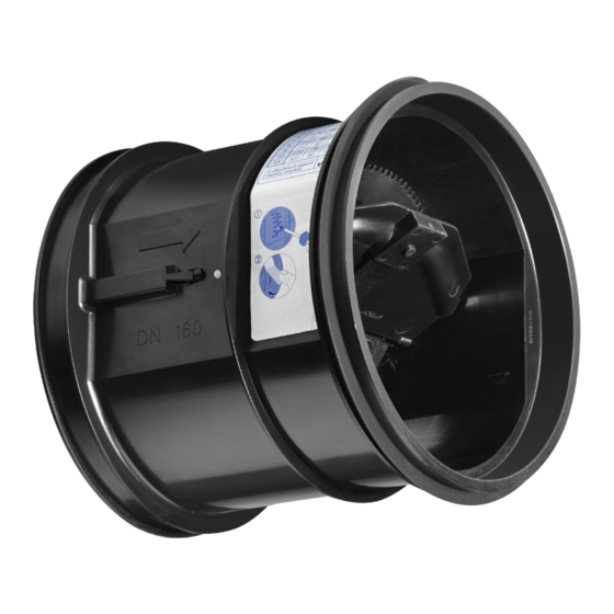
XVFL
X
Aerodynamic damper blade
Sticker showing volume
flow rates
Set the volume flow rate
Insert
VFL-ED for square or
rectangular ducting
(see
accessory options p. 8-10)
–
04/2014
US
Volume Flow Limiters
Type VFL
Volume flow limiter for insertion into ducting
Circular, mechanical self-powered controllers for insertion into ducting,
for the quick and easy balancing of constant volume flow rates in ventilation
and air conditioning systems
Unique damper blade edge for acoustic optimization
Simple and quick commissioning on site
Range of volume flow rate setpoints for each nominal size
Precise and simple setting of volume flow rates using a scale
Best accuracy among controllers for insertion
Suitable for low airflow velocities from 2.6 ft/s
Any installation orientation; maintenance-free
Volume flow limiter accessories for square or
rectangular ducting
Accessories to the VFL now include
Square or rectangular duct adaptor for exhaust or supply orientation (p. 8)
Exhaust register for in-wall installation (p. 9)
Exhaust register with fire damper for in-wall installation (p. 10)
K5 – 2.1 – 1
Advertisement

Related Manuals for Trox VFL


Summary of Contents for Trox VFL
- Page 1 Any installation orientation; maintenance-free Volume flow limiter accessories for square or rectangular ducting Accessories to the VFL now include Square or rectangular duct adaptor for exhaust or supply orientation (p. 8) Exhaust register for in-wall installation (p. 9) Exhaust register with fire damper for in-wall installation (p. 10)
-
Page 2: Table Of Contents
General information Type Page General Information 2.1 - 3-4 Installation Notes 2.1 - 5 Quick Sizing 2.1 - 6 Dimensions and weight 2.1 - 7 Accessories (square/rectangular duct adaptor, exhaust register, 2.1 - 8-10 exhaust register with fire damper) Specification Text 2.1 - 11 Order Code 2.1 - 12... -
Page 3: General Information 2.1
General information Application Construction features Description – Circular volume flow limiters of Type VFL – Circular casing for the simple balancing of volume flow rates – Lip seal for tight and secure fit in air conditioning systems – Acoustically optimized damper blade with –... - Page 4 As the differential pressure changes, the leaf spring adjusts the position of the damper blade such that the volume flow rate is limited. Schematic illustration of the VFL ...
-
Page 5: Installation Notes 2.1
Installation notes Installation Installation The required flow rate is simply set at the point of installation (see page 6 for flow rate set point values). The slot must then be closed with sticker provided to ensure best acoustic performance. The limiter can now be placed into the duct. See Installation, Operation &... -
Page 6: Quick Sizing 2.1
Quick sizing Available volume flow rate setpoint values [m Volume flow rate ranges Volume flow setpoint values The volume flow limiters Size are factory set to the reference volume flow � � rate . Customers can then simply set the required volume flow rate 100 (4") (setting values 1 to 11... -
Page 7: Dimensions And Weight 2.1
Dimensions and weight Dimensional drawing of VFL Dimensions Volume flow limiter Type VFL Dimensions [in] and weight [lb] ØD Weight Nominal size 3¾ 4¾ 4⅝ 5¾ 5⅞ 7¾ 6⅞ 9¾ 8⅝ Installation example for self-balancing of grilles and diffusers Flexible Duct... -
Page 8: Accessories
Volume flow limiter Type VFL (ED & SD) Special features – Exhaust or supply orientation – VFL secured by brackets and sealed to adaptor Typical in-duct installation (VFL-ED shown) Materials and surfaces – Adaptor made of 20 ga. galvanized steel –... - Page 9 Dimensional drawing of VFL - ER and - SR exhaust register without fire damper ¾″ TYP ØD 1½˝ *Dimension "M" is the minimum clearance required at the VFL maximum airflow rate. Clearance can be reduced for lower flow rates. Dimensions [in] Register Units Type VFL-ER and VFL-SR ØD Nominal...
- Page 10 Materials and surfaces – Adaptor made of 20 ga. galvanized steel – Natural finish Dimensional drawing of VFL - ER and - SR exhaust register with fire damper ¾″ TYP ØD 5½ For measurements, reference dimensional chart p. 9 TROX grille dimensions ⅝″...
-
Page 11: Specification Text 2.1
Texts for variants silicone-free bellows. can be provided by Technical data contacting TROX USA. Easy insertion into circular ducts to EN 1506 – Nominal sizes: 4 – 10 in or EN 13180; secure fit ensured by a lip seal. – Volume flow rate range: 11-450 cfm; 5 – 212 l/s Aerodynamically tested and factory set to a or 18 –... -
Page 12: Order Code 2.1
VFL -ER � � � � � VFL size 150 mounted on 8" x 8" exhaust register with grille provided by TROX, adjusted to setpoint 5 (70 cfm). 04/2014 K5 – 2.1 – 12...
Need help?
Do you have a question about the VFL and is the answer not in the manual?
Questions and answers