
Related Manuals for TriContinent Air-Z Premier


Summary of Contents for TriContinent Air-Z Premier
- Page 1 Front cover Product Manual Air-Z Premier Air Displacement Pipette Pump Publication 8694-26 D...
- Page 2 It is believed to be accurate and reliable and is offered as an aid to help in the use of Tricontinent products. It is the responsibility of the user to determine the suitability of the product for the intended use and the user assumes all risk and liability in connection therewith.
-
Page 3: Table Of Contents
Using optional cover ......23 Configure DIP switches ......24 Air-Z Premier Product Manual 8694-26 D... - Page 4 General operating tips ......41 Example pipetting sequence for Air-Z Premier ..42 Command guidelines .
- Page 5 About this chapter ....... . . 127 Pump addressing scheme ......128 Air-Z Premier Product Manual 8694-26 D...
- Page 6 ....... .160 CAN bus evaluation (Air-Z Premier/Flex with full electronics) .
-
Page 7: About This Manual
This comprehensive manual provides the instructions you need to get the Air-Z Premier Air Displacement Pipette Pump installed and operating as desired, as well as to keep properly maintained. Contact information is also included in case you need to reach Tricontinent for assistance. See "Customer support" (page 125). Audience This manual is provided primarily for customers who purchase products from Tricontinent. - Page 8 This page intentionally blank...
-
Page 9: Safety And Standards
Air-Z Premier Air Displacement Pipette Pump. The Air-Z Premier is designed to meet recognized technical regulations and is built with state-of-the-art components. Nevertheless, risks to users, property, and/or the environment can result when it is used carelessly or improperly. -
Page 10: Proper Use Of Equipment
Pipette Pump does not have its own mark. RoHS The Air-Z Premier Air Displacement Pipette Pump is RoHS compliant. It is constructed of components that meet the requirements set by the European Union’s Restriction of Hazardous Substances Directive. The Air-Z Premier Air Displacement Pipette Pump can be affected by exces- sive electromagnetic interference. -
Page 11: Product Overview
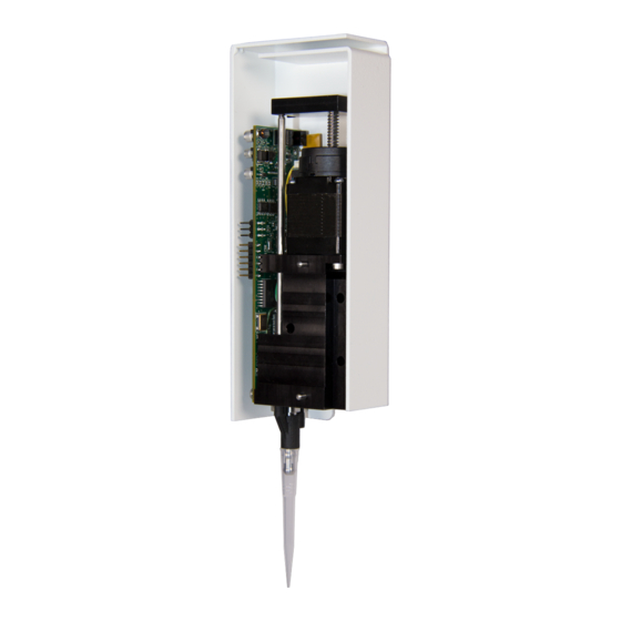
General description Figure 3-1. Typical Air-Z Premier Air Displacement Pipette Pump The Air-Z Premier Air Displacement Pipette Pump is a full-featured, fully pro- grammable air displacement pipette module designed for automated instru- mentation. Utilizing disposable tips, cross contamination and carryover during sample transfer and reagent aliquoting are avoided;... -
Page 12: Features And Facilities
Features and facilities RS232 port to control multiple pumps. Direct RS485 and CAN is also sup- ported in this mode. Alternative modes allow the RS485, RS232, or CAN ports to stream pressure data. In addition, it is possible to configure the pump for standalone operation. - Page 13 Features and facilities Figure 3-2. Facilities on Air-Z Premier pump With optional cover installed Communication/power ribbon cable connector LED indicators Configuration switches Life, blinking Error Indicator lights Life, blinking Error Colors show when associated LEDs are lighted. Disposable tip ejector...
-
Page 14: Key Specifications
C to 40 C (59 F to 104 ° ° • Humidity 20% to 95% RH at 40 C (104 More detailed specifications can be seen at http://www.tricontinent.com. Product data sheets can be downloaded from this location. Product overview Chapter 3... -
Page 15: Installation Instructions
Installation instructions About this chapter This chapter describes how to install your Air-Z Premier Air Displacement Pipette Pump. The following parts are included: • About this chapter, page 15 • Unpacking, page 15 • Before starting, page 16 • Mount pump, page 20 •... -
Page 16: Before Starting
• Optional USB driver for USB/RS485. If you are going to use the USB/ RS485 interface to connect your host PC to the Air-Z Premier, you will need a USB driver, which can be downloaded as described in "Download and install USB driver if needed" (page 18). A Tricontinent USB-to-RS485 converter (0960) is available through Customer Service. -
Page 17: Protocol And Interface Options
Before starting Protocol and interface options Communication standards The Air-Z Premier Air Displacement Pipette Pump uses the following commu- nication standards/interfaces: • RS232 • RS485 • CAN (Controller Area Network) bus. Protocol Three communication protocols are available: • OEM communications protocol •... -
Page 18: Download And Install Usb Driver If Needed
Before starting Download and install USB driver if needed The USB driver is required only when a Tricontinent USB converter is being used to communicate with the Air-Z Premier through the RS485 interface. (This driver is not for the CAN bus interface, which uses a different USB driver supplied with the CAN/USB converter.) -
Page 19: Power And Electrical Considerations
The minimum power supply rating should be confirmed by measurement. Up to eight Air-Z Premier units may be powered from one 24V 4A source, provided that the wire size and the power supply are adequate for the total current and voltage drop. -
Page 20: Mount Pump
Mount pump Mount pump General mounting principles • Install in a stable operating temperature environment. • Mount pump vertically. • Allow adequate airflow for cooling. • Ensure the tip loading station and arm movements are level. Inconsisten- cies will make it difficult to achieve adequate engagement in all rack positions. -
Page 21: Mounting Holes And Dimensions
Refer to Figure 4-1 for general dimensional information, Figure 4-2 for tip adapter location detail, and Figure 4-3 for mounting hole layout. The pump may be secured via three mounting holes and two locating pins. Figure 4-1. Air-Z Premier dimensions Figure 4-2. Tip adapter location information Air-Z Premier Product Manual... - Page 22 Mount pump Figure 4-3. Mounting hole layout Installation instructions Chapter 4...
-
Page 23: Using Optional Cover
Mount pump Using optional cover Installing optional cover An optional cover is available for the Air-Z Premier Air Displacement Pipette Pump. The cover provides a more pleasing appearance and provides some protection of the electronics from accidental bumping or touching. -
Page 24: Configure Dip Switches
Configure DIP switches Configure DIP switches Refer to Tables 4-2 and 4-3 below. The DIP switch settings control device addressing, termination, and communication settings. The AutoRun function, which enables standalone operation, is also enabled or disabled by one of the settings. -
Page 25: Make Electrical Connections
There are several interface signals that cannot be daisy-chained without likely causing damage to the pump electronics. Failure to avoid this type of daisy-chaining may void the warranty. Contact Customer Service if more information is needed. Air-Z Premier Product Manual 8694-26 D... -
Page 26: Pin Assignments For P4
Make electrical connections Pin assignments for P4 Figure 4-6. Connector P4 location P4 pin 1 Table 4-4: Connector P4 pin assignments Function Details 24VDC 24VDC nominal, ±10%, 500 mA peak Ground RS232 TXD line Output data RS232 RXD line Input data I/O 1 Programmable auxiliary output. -
Page 27: Part Information For P4 Mating Connector
Power, communication, and auxiliary connections are shown. • Single-pump cabling as well as multi-pump cabling is shown. • Termination requirements are shown. • Cabling for pressure data streaming is the same as for communication. Only the operation is different. Air-Z Premier Product Manual 8694-26 D... - Page 28 Make electrical connections RS232 cabling RS232 is connected directly to the first pump on the bus. The pump automat- ically converts this to RS485 for communication to all of the other pumps on the bus. Figure 4-7. RS232 cabling Single-pump Installations: Device 1 Device 2 Device 16...
- Page 29 Make electrical connections RS485 bus cabling RS485 may be connected directly or through a USB-to-RS485 converter. Tricontinent offers an appropriate converter for this purpose (catalog num- ber 0960). For converter hookup, see "USB/RS485 converter hookup detail" (page 30). Figure 4-8. RS485 cabling...
- Page 30 Make electrical connections USB/RS485 converter hookup detail The Tricontinent USB/RS485 converter (0960) is used when it is desired to connect to RS485 from a USB port. The converter is provided with a 4-con- ductor ribbon cable assembly and IDC-style plug attached. This may be dis- carded and replaced as needed.
- Page 31 Make electrical connections CAN bus cabling The host PC is typically connected to the CAN bus through a USB-to-CAN converter. Tricontinent offers an appropriate converter kit for this purpose (catalog number 0963), which includes the converter, USB cable, and driver software.
-
Page 32: Confirm Communication With Pump
Confirm communication with pump Confirm communication with pump Before starting • Make sure pump is connected, host PC is connected, and power is applied. • Appropriate driver must be installed as described earlier if using USB for communicating. Confirm with TCS Pump Commander Note: The TCS Pump Commander version 2.1.0 or higher is required for the instructions in this manual. - Page 33 Move DIP switch 8 to the OFF position For the settings to take effect, do one of the following: – Power cycle the pump, or – Send an [!0] command over the initial connection. Air-Z Premier Product Manual 8694-26 D...
-
Page 34: Confirm With Terminal Emulation Program
Initialize pump Confirm with terminal emulation program Open the desired terminal emulation program on the host PC. For RS232/RS485, make sure communication settings are as follows: – Baud rate: 9600, with switch 8 on DIP array SW1 set to the default ON position. -
Page 35: Initialize With Tcs Pump Commander
[Q] command. Check com- munication settings and power, or for something blocking the mech- anism. – Once initialization is successful, the pump is ready to accept com- mands. Air-Z Premier Product Manual 8694-26 D... -
Page 36: Check Led Indicators
Indicator LEDs are provided to assist in monitoring the functioning of the pump. Please refer to Figure 4-11 and Tables 4-5 and 4-6, below, for LED loca- tions and functions. Figure 4-11. LED indicators on Air-Z Premier With optional cover installed... -
Page 37: Insertion Requirements For Disposable Tips
Note: You may obtain a list of recommended and compatible tips from Cus- tomer Service, as well as assistance with selecting the appropriate type of tip for your application. At this time, Axygen® style tips are recommended. Air-Z Premier Product Manual 8694-26 D... - Page 38 This page intentionally blank...
-
Page 39: Operating Instructions
Operating instructions About this chapter This chapter describes how to operate the Air-Z Premier Air Displacement Pipette Pump, once physical and electrical installation has been completed as described in the previous chapter. This chapter includes: • About this chapter, page 39 •... -
Page 40: Operation Overview
Interface requirements are described in the preceding chapter, Installation instructions. The following is a summary. For full information, refer to "Proto- col and interface options" (page 17). Communication standards The Air-Z Premier Air Displacement Pipette Pump uses the following commu- nication standards. • RS232 •... -
Page 41: Operating Tips
After this a delay of 500-2000 ms allows the sheeted fluid to run down the tip walls. Then the dispense is completed, along with the blowout volume. CAUTION: The tip must be empty prior to ejection; otherwise fluid will be dispensed. Air-Z Premier Product Manual 8694-26 D... -
Page 42: Example Pipetting Sequence For Air-Z Premier
Operating tips Example pipetting sequence for Air-Z Premier Note: 1 mL tip, distilled water sample, 175 µL aspirate and dispense. Refer to Figure 5-1. Example is for 1000 µL model. Issue command [A0R]. Moves plunger to position 0 (home). Issue command [V1000R]. Sets plunger velocity relatively high (1,000 increments/sec). -
Page 43: Command Guidelines
Example in DT format: [/2A3143R], where 2 is the device address. There are 16 possible addresses for each Air-Z Premier pump on the bus, set by address switches on the individual pumps. •... -
Page 44: Command Syntax
Command guidelines Command syntax The syntax used in this manual for describing commands in the command set is as shown here: Convention Description [command] The name of the command; the command itself (or a string). Commands are case-sensitive. Square brackets are used to denote any single command or command string. -
Page 45: Execution Controls
In all cases, the [Q] (status query) command may be used to read back errors that have not already been read or returned as part of the command responses. Air-Z Premier Product Manual 8694-26 D... -
Page 46: Initializing Pump
Initializing pump Initializing pump Initialization is required before any move commands will be accepted. Com- mands that do not cause plunger movement do not require pump initializa- tion. These include, for example, velocity settings, report commands, streaming ([f]), pressure calibration ([a]), capacitive detect ([^]), etc. During installation (Chapter 4), an initialization was performed using default settings. -
Page 47: Initialization Commands
Note: Be sure to reinitialize after using the [z] command to ensure correct positioning. CAUTION: Incorrect use of this command can result in unexpected behavior, as the position count will not be referenced to true home (zero) position. Air-Z Premier Product Manual 8694-26 D... -
Page 48: Plunger Movements
Plunger movements The following pages describe how to make plunger movements on the Air-Z Premier Air Displacement Pipette Pump. Arguments for the commands vary according to the increment (resolu- tion) mode. For this reason, the increment mode should be decided upon before programming begins. -
Page 49: Set Plunger Resolution (Increment) Mode (N
µL when assembling a query response. The 1000 µL Air-Z Premier mechanical dis- placement is 0.382 µL per increment. Hence, 3143*0.382=1200.626 illustrates how the stroke length in µL is determined.) - Page 50 µL to increments. Example for 1000 µL Air-Z Premier: (100µL/sec)/(0.382µL/inc) = 261.780 inc/sec The mechanical displacement factor for the 500µL Air-Z Premier is 0.191 µL/ increment. The m and b values shown in the formulas above are set directly with the [x] command or loaded from EEPROM storage using [u18].
- Page 51 [u18_0] will load firmware variable m = 0.955 and b = 6.629 when [u39] and [u40] are at their factory default values. See [u39_x,y] and [u40_x,y] in Table 5-8 (page 94) Note: [?28] reports the [u18] EEPROM values. Air-Z Premier Product Manual 8694-26 D...
-
Page 52: Fluidic Resolution
High resolution micro-increment ment ment mode (16X normal increment mode) Maximum theoretical aspiration volume of the 1000 µL Air-Z Premier is 1200 µL. Maximum theoretical aspiration volume of the 500 µL Air-Z Premier is 600 µL. Operating instructions Chapter 5... -
Page 53: Plunger Movement Commands
Otherwise, fluids can be aspirated into the pump. This can cause damage to sensors and affect pump performance. Always adjust the maximum argument to fit the tip size in use. Note: Maximum allowed stroke can be changed with the configuration com- mand [u1]. Air-Z Premier Product Manual 8694-26 D... - Page 54 Plunger movements Relative pickup (P<n>) The [P] command moves the plunger up (aspirates) the commanded dis- tance <n>. The new absolute position is the previous position plus <n>. Arguments: <n> 0...3143 in normal increment (N0) mode <n> 0...50288 in micro-increment (N1) mode 0...volume in µL <n>...
- Page 55 The [D] command will return an invalid operand error if the final com- manded plunger position is less than 0. 2. In [N2] mode, the plunger travel distance is converted from µL to increments. See "Detailed N2 mode operation" (page 50). Air-Z Premier Product Manual 8694-26 D...
-
Page 56: Configuring Plunger Movement
Plunger movements Configuring plunger movement Configuration commands are used to set up the pump for specific operations. These include settings for plunger velocity, acceleration, backlash, and motor current (motor current settings are factory-only). Velocity and acceleration configuration commands Velocity and acceleration configuration commands are used to control the motion of the plunger. - Page 57 10,000 160,000 12,500 200,000 15,000 240,000 17,500 280,000 20,000 320,000 22,500 360,000 25,000 400,000 27,500 440,000 30,000 480,000 32,500 520,000 35,000 560,000 37,500 600,000 40,000 640,000 42,500 680,000 45,000 720,000 47,500 760,000 50,000 800,000 Air-Z Premier Product Manual 8694-26 D...
- Page 58 Plunger movements Interaction between velocity settings [v], [V], and [c] The velocity settings described below interact according to these rules: • The top velocity [V] must always be equal to or higher than the start velocity [v] and cutoff velocity [c]. •...
- Page 59 Note: This setting can be affected if it is equal to or higher than the top velocity setting [V] or lower than the start velocity [v]. See "Interaction between velocity settings [v], [V], and [c]" (page 58). Air-Z Premier Product Manual 8694-26 D...
- Page 60 Plunger movements Set a defined speed (S<n>) The [S] command sets the top velocity [V] using the predefined speed codes shown in Table 5-4, below. Argument: <n> 0...40 speed code (see Table 5-4 below) {11} power-up default These speeds do not cover the full range of speeds the plunger can travel. They are commonly used velocities provided for convenience.
- Page 61 WARNING! Improper current setting can result in excess heat, which can damage the pump and potentially cause burn injuries if touched. Arguments: <n> 1…100 % of maximum current {50} power-up default argument stored in EEPROM Air-Z Premier Product Manual 8694-26 D...
-
Page 62: Configuring Auxiliary Connections
Configuring auxiliary connections Configuring auxiliary connections Auxiliary pin functions The auxiliary pins on connector P4 can be configured for a variety of func- tions, listed here. For programming details, see [U] commands at "Set pump configuration (U<n>)" (page 92) and the [J] command (described below). For electrical characteristics, see "Pin assignments for P4"... - Page 63 Input. • [U76] = Tip loss high output • [U77] = Tip loss low output Note: When configured as an output, I/O 2 will be reset (de-asserted) if an [r] command is issued. Air-Z Premier Product Manual 8694-26 D...
-
Page 64: Execution Control Commands
Execution control commands Execution control commands Execute command or command string (R) The [R] command tells the pump to execute (run) a new or previously loaded but unexecuted command string. This command will also cause the resump- tion of a halted [H] command string. •... - Page 65 The [T] command immediately terminates any executing command string. If the plunger is moving, it is brought to rest following the deceleration slope set by the [L] command. Clear command buffer (C) The [C] command clears the currently-loaded command string. Air-Z Premier Product Manual 8694-26 D...
-
Page 66: Disposable Tip Commands
Disposable tip commands Disposable tip commands Eject tip (E<n>) The [E] command ejects a tip by moving the plunger in the dispense direc- tion. Once the plunger moves past the home position, it pushes on the tip ejector mechanism. After ejection the plunger returns to the home position, allowing the tip ejector to return to its inactive position. -
Page 67: Liquid Level Detection
Liquid level detection Liquid level detection Overview There are three methods for liquid level detection with the Air-Z Premier: Pressure liquid level detect (pLLD) Pressure liquid level detection uses a pressure sensor to detect pressure changes when the tip contacts a liquid. This requires the pump to be aspirat- ing or dispensing while monitoring for pressure changes. -
Page 68: Liquid Level Detect Commands
Liquid level detection Liquid level detect commands Pressure liquid level detect (pLLD), aspirate or dispense (t<n1>,<n2>) The [t] command allows the pump to detect a liquid (or other) surface. The pump will either aspirate or dispense as specified by <n2>. Once the mea- sured pressure threshold <n1>... - Page 69 It is recommended to start with [V] values in the 50-100 increment/sec range (range varies according to N mode). Air-Z Premier Product Manual 8694-26 D...
- Page 70 Liquid level detection Capacitive liquid level detect, cLLD (^<n>) Note: • This command requires a conductive tip. • The fluid must have significant ionic strength for cLLD to work. • The fluid should be sitting on a ground plane shared with the pump for best results with fluids of very low dielectric strength or when moving very small fluid volumes.
- Page 71 LLD output, I/O 1 will automatically be de-asserted (reset) once the [B] command is issued. It can also be reset using the [r] command. Refer to "Auxiliary pin functions" (page 62). I/O 1 can be configured as either an active high or active low output. Air-Z Premier Product Manual 8694-26 D...
- Page 72 Liquid level detection Set pressure transducer gain (p<n>) The [p] command determines the LLD circuit gain (the gain values are approximate). Arguments: <n> Low gain (p0), where pO is output of pressure transducer <n> Medium-low gain 2 x p0) <n> Medium gain 5 x p0) <n>...
- Page 73 5). Note that this output is automatically reset whenever a [t], [B], or [^] command is issued. I/O 1 must be configured as an LLD output for this com- mand to have an effect. See "Auxiliary pin functions" (page 62). Air-Z Premier Product Manual 8694-26 D...
-
Page 74: Pressure Data Streaming
Pressure data streaming Pressure data streaming Pressure sensor data can be streamed out of the RS232, RS485, or CAN port. This allows for real-time external monitoring of the pressure data, which can be used for the following: • Determining the correct pressure threshold for pLLD •... -
Page 75: Pressure Data Streaming Commands
[u22]. • The [p] command determines the pressure transducer output gain. The [p] command is described on page 72. The other commands listed above are described on the following pages. Air-Z Premier Product Manual 8694-26 D... - Page 76 Pressure data streaming Configure pressure data streaming Streaming is configured as follows: • DIP switch 8 of SW1 must be in the OFF position for pressure data streaming to be allowed. See "Auxiliary pin functions" (page 62). • The commands [U1], [U2], [U3], and [U4] configure the streaming port: –...
- Page 77 If the [+] command is not used, the [u22] command sets the global default streaming continuation period. Example of the [+] command used in a command string: [f1+300A1250f0R] In this example, the [+] command sets a continuation period of 300 ms. Air-Z Premier Product Manual 8694-26 D...
-
Page 78: Operation Validation (Aspirate/Dispense Verify)
Operation validation (aspirate/dispense verify) Operation validation (aspirate/dispense verify) Operation validation monitors aspirate or dispense movements for problems with fluid handling, such as failed aspiration, clogged tips, and wrong fluid volumes moved. Validation can be achieved by externally monitoring and processing real-time pressure streaming data. Alternatively, validation can be achieved automatically using the [q] command as this section describes. -
Page 79: Qualify Next Motion, Time Intersect Method
[u34] Enable or disable air in fluid check. Enabled by default. [u35] Enable or disable bubbles/foam in fluid check. Enabled by default. See "Deriving <n1> and <n2> arguments for the time intersect method" on next page. Air-Z Premier Product Manual 8694-26 D... - Page 80 Operation validation (aspirate/dispense verify) Deriving <n1> and <n2> arguments for the time intersect method Note: The following instructions refer to screens in the TCS Pump Com- mander user interface, Pressure Monitor Window area. The Time intersect screen (Figure 5-2) charts possible changes in pressure during an aspiration move.
- Page 81 TCS Pump Commander (see below). Several identical operations can be run as the results are displayed. For [q] to work well, the pressure trace must be the same each time the same operation is run. Figure 5-4. Pressure Trace Manager screen Air-Z Premier Product Manual 8694-26 D...
-
Page 82: Qualify Next Motion, Pressure Integration Method
Operation validation (aspirate/dispense verify) Error codes generated by time intersect method The time intersect [q] command can generate four possible error codes, as shown below. The codes are reported in response to the [Q] command. Table 5-11 (page 106) has a complete listing of error codes. Error generated by [q<n1>,<n2>] command Error description... - Page 83 [q] command if desired. • The [?156] query reports the pressure area for the last plunger move, whether or not data streaming is on. When data streaming is on, this includes the continuation period described above. Air-Z Premier Product Manual 8694-26 D...
- Page 84 Operation validation (aspirate/dispense verify) • The [?157] query reports the pressure area only for the last streaming move. Consistency of results can be checked with the Pressure Trace Manager in TCS Pump Commander (see below). Several identical operations can be run as the results are displayed.
- Page 85 Set pressure measurement gain to 2. q337,100 Set qualify operation time to 337 milliseconds, and pressure threshold to 100 counts. V4000 Set top velocity to 4000 increments/sec. A1250 Move plunger to absolute position 1250 increments. Run the command string. Air-Z Premier Product Manual 8694-26 D...
- Page 86 Operation validation (aspirate/dispense verify) Pressure integration example: [ap2f1q49V4000A1250f0R] Breakdown: Recalibrate pressure measurement circuitry. Set pressure measurement gain to 2. Enable pressure data streaming. Set qualify operation to 49 count-seconds. V4000 Set top velocity to 4000 increments/sec. A1250 Move plunger to absolute position 1250 increments. Disable pressure data streaming.
-
Page 87: Temperature Compensation
"Set pump/system EEPROM configura- tion parameters (u<n_x>)" (page 94). Also note that the [*] command (page 88) can be used to help determine an optimum value for [u25]. Air-Z Premier Product Manual 8694-26 D... - Page 88 The temperature of the pump body is provided by the built-in temperature sensor of the Air-Z Premier. The ambient temperature is provided by the user each time the command is sent. This command is especially useful when the ambient temperature is con- stantly changing or an executing program causes regular changes in the pump body temperature.
-
Page 89: Using Eeprom
([Z] or [W] commands), the number of tip ejects, the total operating time, the total number of plunger moves, and the total plunger distance moved. Air-Z Premier Product Manual 8694-26 D... - Page 90 Using EEPROM Execute command string stored in EEPROM (e<n>) The [e] command executes the string stored in EEPROM location <n>. Argument: <n> 0...15 EEPROM location 0 through 15 default argument Example: [e0R] will run the string stored in EEPROM location 0. Linking command strings stored in EEPROM Command strings stored in EEPROM can be linked by ending one command string with an [e] command that refers to a second command string.
-
Page 91: Store And Retrieve User Data To/From Eeprom
The [<] command (less-than symbol "<") allows the user to retrieve an 8-bit value stored in up to 16 locations. Note: This function is provided for industry compatibility. Argument: <n> 0...15 EEPROM location Example: Assuming [>0,220] was previously issued, [<0] will return “220.” Air-Z Premier Product Manual 8694-26 D... -
Page 92: Set Pump Configuration (U
Using EEPROM Set pump configuration (U<n>) The [U] command saves pump configuration settings to EEPROM. This command does not require an [R] to execute. The pump configuration settings can be reported by using the [?76] and [?77] report commands. Argument: <n>...) - Page 93 Turn ON Over Pressure error Turn OFF Over Pressure error This setting is ignored if SW 1 switch 8 is in ON position. Defaults shown are active when SW 1 switch 8 is in OFF position. Air-Z Premier Product Manual 8694-26 D...
-
Page 94: Set Pump/System Eeprom Configuration Parameters (U
Using EEPROM Set pump/system EEPROM configuration parameters (u<n_x>) The [u] command stores pump configuration and calibration information in EEPROM. It is similar to the [U] command, may change some of the same parameters as the [U] command, but also allows calibration of other pump parameters.) - Page 95 [u22] setting. 0...5000 u24_x Automatically use temperature compensation. 0 = OFF 1= ON u25_x Temperature compensation rate in increments per °C per mL 12/6 0...50 Note: The [*] command overrides this setting. Air-Z Premier Product Manual 8694-26 D...
- Page 96 Using EEPROM Table 5-8: Pump configuration set with u<n_x> (continued) Factory default µ (x/x =1000 Notes (end µ u<n> value Description, range of _x value of table) u26_x Ambient temperature*100 (e.g., 24 °C*100=2400) to use with 2400 temperature compensation Note: The [*] command overrides this setting. 0...4000 u32_x “Clogged tip”...
-
Page 97: Reset Pump Parameters To Default (!22)
Reset pump (!0) Resets the pump microprocessor. The firmware restarts at the first instruction. This command simulates a power cycle to allow [U] and [u] com- mands (pump configuration EEPROM parameters) to take effect. Air-Z Premier Product Manual 8694-26 D... -
Page 98: Standalone Operation (Autorun)
Standalone operation (AutoRun) Standalone operation (AutoRun) The Air-Z Premier has the ability to operate in standalone mode without a host computer controlling it. First, string(s) are stored in EEPROM using the [s] command. On power-up, the pump checks if the AutoRun switch is enabled. -
Page 99: Report Commands (Query Commands)
Ramp-up acceleration slope code ([L] <n1> argument). Ramp-down deceleration slope code ([L] <n2> argument). Pump motor run current [m] in % of maximum (0-100) Pump motor holding current [h] in % of maximum (0-100) Air-Z Premier Product Manual 8694-26 D... - Page 100 Report commands (query commands) Table 5-10: Report commands (continued) Report command Report description Plunger position in increments, micro-increments, or µL depending on [N] increment mode setting; same as [?0] and [?1] Max. stroke length in increments, micro-increments, or µL depending on [N] increment mode setting Start velocity [v] in increments/sec, micro-increments/sec, or µL/sec depending on [N] increment mode setting;...
- Page 101 COM protocol = Auto detect OEM/DT Stream port = CAN Note: These parameters are stored in EEPROM. At power-up, they will be overridden if the communication configuration switch (DIP switch number 8) is in the ON position. Air-Z Premier Product Manual 8694-26 D...
- Page 102 Report commands (query commands) Table 5-10: Report commands (continued) Report command Report description Pump EEPROM configuration in ASCII text, delimited by “|” • Stroke in µL (microliters) ST_UL • Stroke in increments ST_INC • I/O 2 configuration, GPI,EBRAKE,TIP_H,TIP_L • I/O 1 configuration, LLD_H,LLD_L,GPO •...
- Page 103 [?161] - [?160] will be >= to the [^] command value. ?162 Reports the currently loaded [N2] [u38_1] m value that is in memory. ?163 Reports the currently loaded [N2] [u38_1] b value that is in memory. Air-Z Premier Product Manual 8694-26 D...
-
Page 104: Status And Error Codes
Error codes (bits 0-4) Error codes describe problem conditions that may be detected when operat- ing the Air-Z Premier Air Displacement Pipette Pump. The error codes are listed in Table 5-11 (page 106). • Error codes are returned in the least significant five bits of the status byte (0-4). - Page 105 The [Q] command is used to determine when the command is complete and the pump is ready to accept new commands. There is no need to reinitialize the pump following this type of error. Air-Z Premier Product Manual 8694-26 D...
- Page 106 Error reporting examples Note: Examples are in N0 increment mode. [A7000R] Since <7000> is greater than the stroke of the Air-Z Premier, this returns an error immediately in the command response. When queried with the [Q] command, does not return error.
-
Page 107: Command Summaries
• “None” means there is no default operand, and one must be supplied or an invalid command error will result. RS232/RS485 command summary Table 5-12: Air-Z Premier RS232/RS485 command summary Default Power-up Command Operand <n> range... - Page 108 Command summaries Table 5-12: Air-Z Premier RS232/RS485 command summary (continued) Default Power-up Command Operand <n> range 0perand default Command description Operand/other description Plunger movement commands [A<n>] 0...3143 N0 Move plunger to absolute 0...50288 N1 position. Max argument may be lower if setting of [u1] has 0...1200.626/...
- Page 109 Command summaries Table 5-12: Air-Z Premier RS232/RS485 command summary (continued) Default Power-up Command Operand <n> range 0perand default Command description Operand/other description EEPROM commands [s<n>] 0...15 Store command string in Memory location specified EEPROM location. [e<n>] 0...15 Execute command string from Memory location specified EEPROM location.
- Page 110 Command summaries Table 5-12: Air-Z Premier RS232/RS485 command summary (continued) Default Power-up Command Operand <n> range 0perand default Command description Operand/other description Pressure data streaming commands [f<n>] 0...4 Enable or disable pressure 0 = disable pressure data data streaming streaming...
- Page 111 Command summaries Table 5-12: Air-Z Premier RS232/RS485 command summary (continued) Default Power-up Command Operand <n> range 0perand default Command description Operand/other description [?4] Reports backlash set by [K] command in increments, micro-increments, or µL depending on N increment mode setting.
- Page 112 Command summaries Table 5-12: Air-Z Premier RS232/RS485 command summary (continued) Default Power-up Command Operand <n> range 0perand default Command description Operand/other description [?28] Reports the current [u39] and [u40] EEPROM values. Report lists the coefficients in the order m0,b0,m1,b1,m2,b2,m3,b3 [?29] Reports pump status, busy or idle.
- Page 113 Command summaries Table 5-12: Air-Z Premier RS232/RS485 command summary (continued) Default Power-up Command Operand <n> range 0perand default Command description Operand/other description [?59] Reports lowest recorded pres- sure value since the last [f1] command. [?63] Reports firmware version. Same as [?23] and [&].
- Page 114 Command summaries Table 5-12: Air-Z Premier RS232/RS485 command summary (continued) Default Power-up Command Operand <n> range 0perand default Command description Operand/other description [?91] Reports command string stored in EEPROM location 11. [?92] Reports command string stored in EEPROM location 12.
-
Page 115: Can Bus Command Summary
Command summaries CAN Bus command summary Table 5-13: Air-Z Premier CAN Bus command summary Command Operands Command Description On-the fly commands frame type = 0 Same as RS232/ Set top velocity. RS485 Terminate command execution. Action commands frame type = 1 All RS232/RS485 action commands are valid in CAN bus mode. - Page 116 This page intentionally blank...
-
Page 117: Maintenance
• Routine maintenance, page 117 • Cleaning method recommendations, page 118 Note: There are no replaceable components on the Air-Z Premier Air Dis- placement Pipette Pump. Routine maintenance The following maintenance tasks should be performed regularly to ensure that the pump remains in good condition. -
Page 118: Cleaning Method Recommendations
Cleaning method recommendations Cleaning method recommendations The Air-Z Premier Air Displacement Pipette Pump may be cleaned as follows. • Pump body and tip adapter: use cleaners compatible with anodized alu- minum pump body and stainless steel tip adapter. • Exposed printed circuit boards: An air spray product can be used to remove dust. -
Page 119: Troubleshooting
Troubleshooting About this chapter This chapter provides troubleshooting guidance for the Air-Z Premier Air Dis- placement Pipette Pump. The following parts are included: • About this chapter, page 119 • Symptoms and solutions, page 120 • Error codes and corrective action, page 123... -
Page 120: Symptoms And Solutions
Symptoms and solutions Symptoms and solutions See Table 7-1 for common symptoms and their remedies. Also see Table 7-2 for any error codes that are received. Table 7-1: Troubleshooting Symptom Possible cause(s) Corrective action Unit runs automatically AutoRun switch set to standalone •... - Page 121 (error code 6) has been issued. The [t] command plunger move- Break Z-axis motion into segments, and ment may have completed before Z reset pLLD command before each seg- axis travel has completed. ment. Air-Z Premier Product Manual 8694-26 D...
- Page 122 Symptoms and solutions Table 7-1: Troubleshooting (continued) Symptom Possible cause(s) Corrective action Daisy-chaining of pressure Wrong communications protocol in Use CAN protocol for multiple-pump data streaming not available. use for multiple-pump pressure data streaming. streaming. Only CAN allows multiple-pump streaming. Tip eject failure Tip not installed or pressed on too See "Insertion requirements for dispos-...
-
Page 123: Error Codes And Corrective Action
[E] was issued. Tip pressed on too hard. 2 blinks Plunger overload Movement of plunger is Re-initialization required. Check for excessive back blocked. pressure or something obstructing movement of pump mechanism. Air-Z Premier Product Manual 8694-26 D... - Page 124 Error codes and corrective action Table 7-2: Error codes and corrective action (continued) Error Error Code pattern Error Description/possible cause Corrective action Tip loss Unexpected tip loss. Tip may Re-install tip with appropriate force. Refer to "Dispos- not be pressed on hard able tip installation force and speed"...
-
Page 125: Customer Support
Gardner Denver Thomas Pneumatic Systems (Wuxi), Co., Ltd. No. 1 New Dong An Road, Shuofang Town Wuxi, Xinwu District, Jiangsu 214142 China Tel: +86 510 6878 2258 Fax: +86 510 6878 2200 tricontinent.cn@gardnerdenver.com Website: http://www.tricontinent.com Air-Z Premier Product Manual 8694-26 D... -
Page 126: Ordering Parts And Accessories
Ordering parts and accessories To view and/or download detailed product and accessory information and lit- erature, please go to the product page for the Air-Z Premier Air Displacement Pipette Pump at www.tricontinent.com. Typical Information at this location may include the following: •... -
Page 127: About This Chapter
Reference information About this chapter This chapter contains reference information to support use of the Air-Z Premier Air Displacement Pipette Pump. The following subjects are included: • About this chapter, page 127 • Pump addressing scheme, page 128 • OEM communication protocol, page 129 •... -
Page 128: Reference Information
Pump addressing scheme Pump addressing scheme As part of the communications protocol, every command string contains an address for the intended pump(s). The address corresponds to a device number set by switches on the pump. There are 16 possible addresses for a pump. For RS232, RS485, and CAN, the overall hexadecimal addressing scheme is shown in Table 9-1. -
Page 129: Oem Communication Protocol
Any characters transmitted outside the command block protocol are ignored. SYNC (FFh) Used for backward compatibility with older model pumps. STX (Ctrl B or 02h) The STX character indicates the beginning of a command string. Air-Z Premier Product Manual 8694-26 D... - Page 130 OEM communication protocol Pump address The pump address is specific, selected on each individual pump, as described in the instructions for that pump. Sequence number/repeat flag The sequence number is a single byte that conveys both a sequence number (legal values: 0 through 7) and a bit flag indicating that the command block is being repeated due to a communications breakdown.
- Page 131 REP: Value is 0 for non-repeated command, 1 for repeated. SQ0 - SQ2: Sequence value, as shown below: Sequence Value Data block (length n bytes) The data block consists of an ASCII string of commands sent to the pump. Air-Z Premier Product Manual 8694-26 D...
-
Page 132: Oem Protocol Answer Block Characters
OEM communication protocol ETX (Ctrl C or 03h) The ETX character indicates the end of the command string. Command block checksum The checksum is the last byte of the message string. All bytes (excluding line synchronization and checksums) are XORed to form an 8-bit checksum. This is appended as the last character of the block. - Page 133 For example, if the host were to send the [Q] command to the device at address 1, in hexidecdimal “pump’s “idle” response would be Ox02, 0x30, 0x60, 0x03, 0x51. The checksum for the first four bytes is 0x51. Air-Z Premier Product Manual 8694-26 D...
-
Page 134: Data Terminal (Dt) Protocol
Data Terminal (DT) protocol Data Terminal (DT) protocol The DT protocol can be used easily from any terminal or terminal emulator capable of generating ASCII characters at 9600 or 38400 baud, 8 bits, and no parity. Table 9-4 lists each setting of the DT protocol. Table 9-4: DT Protocol communication details Serial bus configuration Parameter... -
Page 135: Dt Protocol Answer Block Characters
This is the response from all report commands with the exception of the [Q] command. The ETX character (Ctrl C or 03h) indicates the end of the response string. End character(s) The carriage return (“CR” or 0Dh) and line feed (“LF” or 0Ah) terminate the reply block. Air-Z Premier Product Manual 8694-26 D... -
Page 136: Can Interface Communications
CAN interface communications CAN interface communications CAN (Controller Area Network) is a two-wire, serial communication bus. It eliminates polling sequences that verify task completion. Using CAN, the pumps asynchronously report to the master host when they have finished the current task. Note: The pumps use a CAN controller and transceiver chip compatible with Philips Semiconductor CAN bus specification, version 2.0. - Page 137 There can be up to 16 devices in the group, with addresses from 0 to 15. Expressed in binary, these would be b0000 through b1111. In hexadecimal, they would be 0h through 0Fh. Air-Z Premier Product Manual 8694-26 D...
- Page 138 CAN interface communications RTR, IDE, r0 CAN arbitration field CAN control field Data Length data Direction Group Device Frame (DLC) block XXXX XXXX bytes The RTR, IDE, and r0 bits are not used in this CAN implementation and should always be set to 0. Data length code (DLC) CAN arbitration field CAN control field...
- Page 139 If less than 8 bytes of data are required to complete the pump com- mand, a Type 4 frame is unnecessary; the command will start with a Type 3 message and complete with an action or report frame type. Air-Z Premier Product Manual 8694-26 D...
- Page 140 CAN interface communications Note: The last frame of a multi-frame message for action commands will be type 1. The last frame of a multi-frame message response from the pump for report commands will be type 6. Type 5: Event Messages. Frame bits = 101 Type 5 frames are used to send unsolicited messages from the pump.
- Page 141 Always 0 in boot response Frame = 0 Boot request response frame RTR/IDE/r0 = 0 All three always 0 Length = 2 Two data bytes in return message Note: Boot MID is the same for all nodes. Air-Z Premier Product Manual 8694-26 D...
- Page 142 CAN interface communications Example 2. The pump address DIP switches are set to address 6. Pump sends boot request: Direction Group Device Frame RTR/IDE/r0 Length 0110 0000 Host acknowledges: Direction Group Device Frame RTR/IDE/r0 Length Data bytes Node ID Slave ID 0000 0010 0010 0110 0010 0110...
- Page 143 = 1, the master must wait for the answer with frame type = 1 before issuing the next com- mand with frame type = 1. If a second command of the same type is sent with- Air-Z Premier Product Manual 8694-26 D...
- Page 144 CAN interface communications out waiting, a command overload status results. Commands with different frame types can be in progress at the same time (e.g., an action command and a query command). Example host/pump exchanges The following are typical exchanges between the host and pump for action commands, multi-frame commands, common commands, and query com- mands.
- Page 145 0001 0x31 (“1”) Pump acknowledges: Direction Group Device Frame RTR/IDE/r0 Type 0000 0000 After executing the command, pump reports status: Direction Group Device Frame RTR/IDE/r0 Data bytes Type 0000 0010 0x60 0x00h (“ 0”) Air-Z Premier Product Manual 8694-26 D...
- Page 146 CAN interface communications Query command examples Example: the host sends report command 29 of frame type 6 to a pump, with the pump Slave ID set to Group 2, device address 1. Host sends: Direction Group Device Frame RTR/IDE/r0 Data bytes Type 0001 0010...
- Page 147 After parsing the command and finding an error (in [N0] mode, an abso- lute move of 4000 is not supported), the pump reports status of 0x63 (invalid operand): Direction Group Device Frame RTR/IDE/r0 Data bytes Type 0000 0010 0x63 0x00h (“ 0”) Air-Z Premier Product Manual 8694-26 D...
-
Page 148: Oem And Dt Timing And Polling Guidelines
OEM and DT timing and polling guidelines OEM and DT timing and polling guidelines Master/slave relationship • For OEM and DT protocol, the host controller (host) and pump have a master/slave relationship. The pump never sends a message to the host independently;... -
Page 149: Polling Alternatives
I/O 1 high. The host can monitor this signal and query status after it transitions high. • CAN bus communication is event driven, making polling unnecessary. Also, CAN bus bandwidth is much higher. Air-Z Premier Product Manual 8694-26 D... -
Page 150: Tcs Pump Commander Overview
2.1.0, which runs on Windows 7 and Windows 10 operating systems. Features • This version of TCS Pump Commander supports Tricontinent liquid-han- dling syringe or air displacement pumps. • Commander connects with and recognizes the pump it is connected to... -
Page 151: Windows
Commands and the pump’s response when polled are shown. By default, TCS Commander opens to this window. Many of the other window configurations include the String Sequencer, so that real-time charting and data may be observed as commands are issued. Air-Z Premier Product Manual 8694-26 D... - Page 152 The Streaming Data Chart shows streaming data from an Air-Z pump in real time. The chart shows moving plunger position, pressure count, and optionally capacitive count (Air-Z Premier only). This information assists in determining optimal settings for liquid level operations.
- Page 153 A tab at the bottom of the Pressure Trace Window takes you to this item. Two forms of the tool are available. Only one of them however, is recom- mended, as explained in the help documentation. The product manual con- tains detailed instructions for operation validation. Air-Z Premier Product Manual 8694-26 D...
- Page 154 TCS Pump Commander overview String Sequencer + Tip Performance Chart Window (Air-Z only) The Tip Performance Chart is a tool that predicts fluid aspiration for a given tip and fluid operation, and gives the user command parameters needed to more accurately use the Air-Z pump's [N2] operating mode (sending com- mands in uL units).
- Page 155 The Trape- zoidal Motion Window is configured to display with the String Sequencer window. Plunger motion settings are described in the product manual. Air-Z Premier Product Manual 8694-26 D...
- Page 156 TCS Pump Commander overview String Sequencer +Valve Viewer Window (Syringe pumps only) The Valve Viewer shows the current and available valve positions for the con- nected pump as commands are selected. The interior of the valve is shown as well, so the user can see the fluid path change as valve positions change. This can be useful as most valves are opaque, with no visual means to know or verify the current valve position.
-
Page 157: Evaluation Cables And Accessories
Evaluation cables and accessories Evaluation cables and accessories This section identifies the cables and accessories needed for evaluating the Tricontinent Air-Z Premier and Flex pump products. Several scenarios are described. Obtaining needed items. Items listed here can be obtained through Customer Service or as otherwise described. -
Page 158: General-Purpose Evaluation Cables
• Evaluation cable set 10388 is for the Air-Z Flex with full electronics and the Air-Z Premier. It consists of a 10-position flex cable, interface PCBA, and 10-position connector with 18” flying leads for the pump interface. The user is responsible for providing a 24V 500 mA power supply and the interface signals to be used with the pump. -
Page 159: Rs232 Evaluation
Evaluation cables and accessories RS232 evaluation (Air-Z Premier/Flex with full electronics) Items needed • Evaluation cable set 10389, which consists of a 10-position flex cable, interface PCBA, and cable assembly for connection to RS232, RS485/ USB, and CAN bus/USB •... -
Page 160: Usb/Rs485 Evaluation
Evaluation cables and accessories USB/RS485 evaluation (Air-Z Premier/Flex with full electronics) Items needed • Evaluation cable set 10389, which consists of a 10-position flex cable, interface PCBA, and cable assembly for connection to RS232, RS485/ USB and CAN bus/USB •... -
Page 161: Can Bus Evaluation
Evaluation cables and accessories CAN bus evaluation (Air-Z Premier/Flex with full electronics) Items needed • Evaluation cable set 10389, which consists of a 10-position flex cable, interface PCBA, and cable assembly for connection to RS232, RS485/ USB, and CAN bus/USB. -
Page 162: Can Bus Data Streaming Example With
Evaluation cables and accessories CAN bus data streaming example with serial control The option exists to stream pressure data from the pump. The optimum method for streaming is to use the CAN bus interface due to its higher data rate. In the application described here, the pump is controlled through either RS232 or RS485/USB. -
Page 163: Revision History
Previous version incorporated and information expanded to form a full product manual. Corrections made as needed. Latest firmware changes (through 5/30/2019) included. 8/20/2021 Brought instructions up to date with V13 firmware (3/14/2020). Changed instructions where procedures interface with new version of Commander (TCS Pump Commander). Air-Z Premier Product Manual 8694-26 D... - Page 164 The information presented in this material is based on technical data and test results of nominal units. It is believed to be accurate and reliable and is offered as an aid to help in the selection of Tricontinent products. It is the responsibility of the user to determine the suitability of the product for the intended use and the user assumes all risk and liability in connection there with.
Need help?
Do you have a question about the Air-Z Premier and is the answer not in the manual?
Questions and answers