
Related Manuals for TriContinent C3000


Summary of Contents for TriContinent C3000
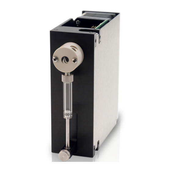
- Page 1 Cover page Product Manual C-Series Precision Syringe Pumps C3000 C3000MP C24000 C24000MP C3000MP C2400MP...
- Page 2 Copyright© 2017, Gardner Denver TriContinent . All rights reserved. NOTICE The information presented in this material is based on technical data and test results of nominal units. It is believed to be accurate and reliable and is offered as an aid to help in the use of TriContinent products.
-
Page 3: Table Of Contents
Contents 1 About this manual Introduction ........7 Audience . - Page 4 Make electrical connections ......24 Connector J3 pin assignments ..... 24 Install communication/power cabling.
- Page 5 Execution control commands ......71 Using EEPROM ........76 Report commands (query commands) .
- Page 6 CAN interface communications ..... . 113 CAN messages ........113 TCS Pump Commander quick reference guide .
-
Page 7: About This Manual
This comprehensive manual provides the instructions you need to get the C-Series Precision Syringe Pumps installed and functioning, put into operation, and properly maintain. Contact information is also included in case you need to reach TriContinent for assistance. See "Customer sup- port" (page 103). Audience This manual is provided primarily for customers who purchase products from TriContinent. - Page 8 This page intentionally blank...
-
Page 9: Safety And Standards
Safety and standards About this chapter This chapter contains safety notifications used in this manual, cautions about proper use of the equipment, and standards with which the C-Series Precision Syringe Pumps comply. The C-Series Precision Syringe Pumps are designed to meet recognized technical regulations and are built with state-of-the-art components. -
Page 10: Proper Use Of Equipment
Note: It is the responsibility of the purchaser to determine the suitability of an application and material compatibility of the products. Regulatory notices The TriContinent C-Series Precision Syringe Pumps are general labora- tory components. Because they are not medical devices, they are not subject to FDA approval. -
Page 11: Product Overview
The C-Series pumps utilize standard communication interfaces and methods for mounting used by other compact syringe pump designs. The pumps are outfitted with TriContinent long-life valves available in various configurations and material combinations. All C-Series pumps can be customized for specific liquid handling needs. -
Page 12: Features And Facilities
The C-Series hardware and firmware automatically detect the communication interface and communication protocol. The pump can be configured to operate at different communication speeds. There are currently four models of the C-Series Precision Syringe Pumps: C3000. C3000MP, C24000, and C24000MP. C3000. -
Page 13: Key Specifications
C to 40 C (59 F to 104 ° ° • Humidity 20 to 95% RH at 40 C (104 More detailed specifications can be seen at http://www.tricontinent.com. Product data sheets can be downloaded from this location. C-Series Product Manual... - Page 14 This page intentionally blank...
-
Page 15: Installation Instructions
Installation instructions About this chapter This chapter describes how to install your C-Series Precision Syringe Pumps. This chapter contains the following parts: • About this chapter, page 15 • Unpacking, page 15 • Before starting, page 16 • Place or mount pump(s), page 20 •... -
Page 16: Before Starting
If you are going to use the USB port of your host computer to connect to the C-Series pump, you will need a USB-to-RS485 converter, which can be ordered through TriContinent Customer Service. • A software interface for communicating with the pump or pumps. -
Page 17: Protocol And Interface Options
Before starting Protocol and interface options Protocol Three communication protocols are available: • OEM communications protocol • Data Terminal (DT) protocol • CAN protocol The C-Series firmware automatically detects which protocol is in use. Communication standards The C-Series Precision Syringe Pumps use the following communication standards. -
Page 18: Obtain And Install Tcs Pump Commander If Needed
You will be provided with further instruc- tions. Download and install USB driver if needed The USB driver is required only when the TriContinent USB converter is being used to communicate with C-Series Precision Syringe Pumps. If using other third-party USB converters, follow their instructions for downloading and installing drivers. -
Page 19: Power And Electrical Considerations
Before starting Power and electrical considerations The C-Series pump has the following power requirements: • Input voltage: 24 VDC ± 10%. • Input current; 1.5 A peak current max., 650 mA average (RMS) current max., and 100 mA typical idle current. Power supply requirement for single pump The 24V DC supply for a single C-Series pump should meet the following requirements:... -
Page 20: Place Or Mount Pump(S)
Place or mount pump(s) Place or mount pump(s) Before mounting Termination jumper J9 is located on the bottom of the pump. To avoid later inconvenience during installation, make sure it is set correctly for your situation before securing the pump on a surface. Proper termina- tions are indicated in "Install communication/power cabling"... - Page 21 Place or mount pump(s) Figure 4-3. Mounting holes and dimensions .603 4 holes (15.3) .183 .200 (4.6) (5.1) 1.384 1.750 (35.1) (44.4) .160 (4.0) .603 .300 4 holes both sides, for .875 (15.3) (22.2) (7.6) .300 .200 total of 8 holes (7.6) (5.1) 5.00...
-
Page 22: Set Configuration Jumpers And Address Switch
Set configuration jumpers and address switch Set configuration jumpers and address switch Configuration jumpers Before operating the pump, jumpers J2 and J9 must be set as appro- priate for your system. Refer to the tables below and Figure 4-4. Table 4-2: J2, various options Jumper Segment Function... -
Page 23: Can Baud Rate
Set configuration jumpers and address switch CAN baud rate Default is 100K bps. For initial installation and operation, this should be left unchanged. Once communication has been established, it may be changed as described in Table 5-9 (page 79). Figure 4-4. Configuration jumpers and address switch Do not plug or unplug DB-15 connector with power applied or damage may result. -
Page 24: Make Electrical Connections
Make electrical connections Make electrical connections Connector J3 pin assignments All electrical connections, including power, communication, and control signal IO are made through 15-pin D-sub connector J3. This connector is located on the back of the pump. Mating connector and shield informa- tion is provided in the tables below. -
Page 25: Install Communication/Power Cabling
Make electrical connections Install communication/power cabling Cabling multiple pumps Make connections as shown in the following diagrams. Each bus can support up to 15 devices in daisy-chain fashion. The diagrams show con- nections, address switch settings, and termination jumper positions. Cabling a single pump For single-pump installations, refer to the cabling diagrams and follow the instructions for single-pump installations in the diagrams. - Page 26 Make electrical connections RS232 cabling Cabling for RS232 goes from the host controller serial port to the first pump on the bus. There it is converted by the pump electronics to/from RS485 for remaining pump connections. Figure 4-5. RS232 communication and power cabling Single-pump Installations: Make input and power connections as shown for Device 1.
- Page 27 Make electrical connections RS485 cabling This would typically go from a PC USB port through the optional USB- to-RS485 converter to the RS485 bus. However, it can also come directly from an RS485 host controller. Figure 4-6. RS485 communication and power cabling Single-pump Installations: Make input and power connections as shown for Device 1.
- Page 28 Make electrical connections CAN BUS cabling CAN cabling is direct from a CAN BUS controller to the CAN bus on the J3 connectors. Figure 4-7. CAN BUS communication and power cabling Single-pump Installations: Make input and power connections as shown for Device 1. Leave CAN termination jumper installed.
-
Page 29: Control Wiring (Auxiliary Inputs And Outputs)
J2. Refer to Figure 4-4 (page 23) if necessary. Click the Connect button and see the response in the Status window. – The response format is OK: C3000 MMDDYY for both the C3000 and C24000 models. Example: OK: C3000 052914, where 052914 represents the date of the firmware. -
Page 30: Confirm With Terminal Emulation Programs
So if the Address Switch is set to zero, use /1. This command string requests the firmware version of the pump. – The response format is C3000 MMDDYY for both the C3000 and C24000 models. Example: C3000 052914, where 052914 represents the date of the firmware. -
Page 31: Initialize With Tcs Pump Commander
Initialize pump Initialize with TCS Pump Commander Issue the [Z] command. Observe pump: – The plunger arm/holder should move, and the valve will turn. An “OK” message should appear in the Status: Response window at the top of the screen. Most of the LEDs at the top of the pump should be lit. -
Page 32: Check Led Indicators
Initialize pump Check LED indicators Diagnostic LEDs are provided to assist in monitoring the functioning of the pump. Please refer to Figure 4-8, below. Note: • Valve sensor LEDs indicate either at home or in other designed position. • The solenoid LED is not functional. •... -
Page 33: Install Syringe
Syringe and Plunger. – C3000 pumps: if the pump is powered off, manually lower the Plunger by pushing firmly down on the Syringe Plunger Arm/Holder. If the power is on, this can be done by sending the command [A3000R]. -
Page 34: Connect Tubing
Connect tubing Figure 4-9. Installing syringe Valve Screw Syringe clockwise to seat in Valve body. Syringe Pull Plunger down all the way Plunger into Syringe Plunger Arm/Holder. Plunger Lock Screw Turn Plunger Lock Screw Syringe Plunger Arm/Holder clockwise to tighten. Connect tubing CAUTION: Be sure to check fluid compatibility with the materials in the... -
Page 35: Operating Instructions
Operating instructions CAUTION: After connecting fluids, the initialization command will result in fluid movement. Make sure the pump is properly plumbed and there are no leaks. Otherwise this fluid movement can result in spills. Always run liquid through the syringe and valve when issuing a move command. -
Page 36: Operation Overview
Operation overview Operation overview Operation consists of: • Initializing the pump with input/output ports defined for your application • Priming syringe and tubing • Programming the moves and making the settings that are described following "Priming syringe and tubing" Interface requirements review Interface requirements are described in the preceding chapter, Installation instructions. -
Page 37: Command Guidelines
Command guidelines Command guidelines The C-Series features a robust command set which allows a wide range of pump actions. Many of the commands have default arguments; these are frequently-used values that, when used, can help minimize the length of command strings. Take a moment to familiarize yourself with each com- mand in order to obtain the best performance for your application. -
Page 38: Command Syntax
Command guidelines Command syntax The syntax used in this manual for describing commands in the command set is as shown here: Convention Description [command] The name of the command; the command itself (or a string). Commands are case-sensitive. <n> Operand (command argument). For example, [A]<n> represents the A (absolute move) command and operand <argument>. -
Page 39: Command Execution Guidelines
Command guidelines Command execution guidelines To enter commands properly, keep the following in mind: • Commands are case-sensitive. • All commands, except report commands and most control commands, must be followed by an [R] (Run or Execute) command. • Single or multiple commands can be sent to the pump within a string. For example: –... -
Page 40: Initializing Pumps
Initializing pumps Initializing pumps During installation, an initialization was performed using default settings. Your application is likely to require more specific settings than those the defaults provide. This section describes the initialization sequence, and the commands and options available for customizing the initialization settings to accommodate your application. -
Page 41: Initialization Commands
Initializing pumps Initialization commands Initialize pump, set valve output to the right (CW polarity) (Z<n1,n2,n3>) The [Z] command initializes the plunger drive and sets a non-distribution type valve output to the right (as viewed from the front of the pump). If a distribution valve is configured, <n2>... - Page 42 Initializing pumps Argument <n2> options: <n2> options Description Set the input initialization port to 1 (default). 1...X Set the input initialization port to a non-default port. X = number of ports on the valve. Argument <n3> options: <n3> options Description Set the output initialization port to X (default).
- Page 43 Initializing pumps All speeds refer to defined speeds described in the description for the [S] command (page 66). Speeds can be changed from default initialization speeds. Slower initialization speeds may be useful when working with vis- cous fluids or small I.D. (inner diameter) tubing. Argument <n2>...
- Page 44 0...120 increments in N0 mode <n> 0...960 increments in N1 or N2 mode (micro-increments) {24} Power-up default C3000/C3000MP {384} Power-up default C24000/C24000MP For example, to offset 10 increments away from the zero position, send the following string: [k10ZR] Since [k] only takes effect on initialization, the [k] command is usually fol- lowed by an initialization command, [Z] or [Y] as shown on previous pages.
-
Page 45: Priming Syringe And Tubing
Priming syringe and tubing Priming syringe and tubing Priming prepares the system for operation by removing air from the syringe and tubing. Run the pump with a full stroke and several cycles to prime the system with the working fluid (e.g. water). The following example is in DT protocol. Example priming string: [ZV6000gIA3000OA0G3R] Initialize [Z];... -
Page 46: Valve Movements
Valve movements Valve movements Valve selection information The following valve selection instructions are provided for informational purposes, and may be helpful in identifying which pump the instructions in the following section ("Making valve movements") apply to. No valve selection by the user is needed as this is set by the factory, along with the valve jumper on J2. -
Page 47: Movements For Non-Distribution Valves
Valve movements Descriptions of commands for each type of valve are followed by illustra- tions which show positions resulting from each command. Note: The illustrations on the following pages show valve positions as viewed from the front of the pump. Movements for non-distribution valves (3-port and 4-port) The following commands apply to the 3-port 120°... - Page 48 Valve movements ° Figure 5-10. Positions for 3-port 120 Y valve (U1 config) Syringe port located at bottom of valve 3-port commands using 3-port commands using Z initialization Y initialization I valve command I valve command sets input to the right sets input to the left O valve command O valve command...
- Page 49 Valve movements ° Figure 5-11. Positions for 4-port 90 valve (U2 config) Syringe port located at bottom of valve 4-port commands using 4-port commands using Z initialization Y initialization I valve command I valve command sets syringe input to the left sets syringe input to the right O valve command O valve command...
-
Page 50: Movements For T Valves (3-Port And 4-Port)
Valve movements Movements for T valves (3-port and 4-port) The following commands apply to the 90° 3-port T and 90°, 4-port T valves. Refer to also to Figure 5-12, which shows valve positions according to valve movement and initialization commands for the 3-port and 4-port T valves. Move valve to input position (I) The [I] command moves the valve to the input position. - Page 51 Valve movements Figure 5-12. Positions for 3-port and 4-port T valves (U5 config) Syringe port located at bottom of valve T-port commands T-port commands using Z initialization using Y initialization 4-port valve top port I valve command sets input to the left I valve command sets input to the right On 4-port valve, top port also connected On 4-port valve, top port also connected...
-
Page 52: Movements For Distribution Valve (3-Way With U4 Config)
Valve movements Movements for distribution valve (3-way with U4 config) The following commands apply to the 3-way distribution valve as it behaves when set with the U4 EEPROM configuration command (see "Valve selec- tion information" on page 46.) In this configuration, the three distribution ports are referred to as left, right, and top. - Page 53 Valve movements Figure 5-13. Positions for 3-way distribution valve (U4 config) Syringe port located at bottom of valve 3-way distribution commands 3-way distribution commands using Y initialization using Z initialization I valve command I valve command connects syringe to the right port connects syringe to the left port O valve command O valve command...
-
Page 54: Movements For Distribution Valves
Valve movements Movements for distribution valves (3-way with U11 config; and 6-way) The commands below apply to two distribution valves: • The 3-way distribution valve when configured with the U11 command • The 6-way distribution valve For these valves, the distribution ports are numbered from the left or right, depending on whether the Z or Y initialization preceded the positioning commands. - Page 55 Valve movements Figure 5-14. Positions for 3-way distribution valve (U11 config) Syringe port located at bottom of valve 3-way distribution commands 3-way distribution commands using Z initialization using Y initialization I <1> or O <1> connects I <1> or O <1> connects syringe to port 1 syringe to port 1 O <2>...
- Page 56 Valve movements Figure 5-15. Positions for 6-way distribution valve (U7 config) Syringe port located at bottom of valve 6-way distribution commands 6-way distribution commands using Z initialization using Y initialization I <1> or O <1> connects I <1> or O <1> connects syringe to port 1 syringe to port 1 I <2>...
-
Page 57: Movements For 4-Port Loop Valve
Valve movements Movements for 4-port loop valve The following commands apply to the 4-port loop valves (see "Valve selec- tion information" (page 46). In this configuration the four ports are referred to as left, right, top, and syringe. Refer also to Figure 5-16 (page 58), which shows valve positions according to valve movement and initialization commands for the 90°... - Page 58 Valve movements Figure 5-16. Positions for 4-port loop valve (U9 config) Syringe port located at bottom of valve Loop valve commands using Loop valve commands using Z initialization Y initialization I valve command I valve command connects left port to syringe, connects top port to right port, and right port to top port and left port to syringe...
-
Page 59: Plunger Movements
1 mL syringe on C24000 in N0 mode: volume = 1000 L/24000 = 0.0417 L/increment µ µ • 1 mL syringe on C3000 in N1 or N2 mode: volume = 1000 L/24000 = 0.0417 L/increment µ µ • 1 mL syringe on C24000 in N1 or N2 mode: volume = 1000 L/192000 = 0.0052... -
Page 60: Set Plunger Resolution (Increment) Mode (N)
N2, micro-increment mode for both positioning and velocity Power-up default Increment mode vs. full stroke: Increment Increments/full stroke, Increments/full stroke, Mode C3000/C3000MP C24000/C24000MP 3,000 increments 24,000 increments 24,000 (8 * 3,000) 192,000 (8 * 24,000) 24,000 (8 * 3,000) 192,000 (8 * 24,000) Note: •... -
Page 61: Plunger Move Commands
Plunger movements Plunger move commands Move plunger to absolute position (A<n>) The [A] command moves the plunger to absolute position <n>. Arguments for C3000/C3000MP: <n> 0...3000 increments in N0 mode <n> 0...24000 increments in N1 or N2 mode (micro-increments) default argument Arguments for C24000/C24000MP: <n>... - Page 62 Plunger movements Make relative dispense (D<n>) The [D] command moves the plunger upward the number of increments <n> commanded. The new absolute position is the previous position minus <n>. Arguments for C3000/C3000MP: <n> 0...3000 increments in N0 mode <n> 0...24000...
-
Page 63: Controlling Plunger Moves With Configuration Commands
Since the C24000 and C24000MP have a 4 times finer lead screw pitch than the C3000/C3000MP, the linear velocity is 1/4 as fast for a given velocity setting. Thus, to aspirate/dispense at the same rate, the Top Velocity command [V] needs to be multiplied by 4 for the C24000/C24000MP. - Page 64 Plunger movements Set acceleration/deceleration slopes (L<n>) During the beginning and end of a move, the plunger speed ramps up and down respectively. The ramp is programmed using the Set Slope [L] com- mand. It is calculated as <n> x 2,500 increments/sec^2. Arguments (slope codes): <n>...
- Page 65 <n> 1...48000 increments/sec, N2 mode (micro-increments) {1400} power-up default, C3000/C3000MP {5600} power-up default, C24000/C24000MP The top velocity can be changed “on the fly,” that is, while the plunger is moving, using the [V] command. When the move completes, the speed value reverts back to its original value.
- Page 66 Plunger movements Set cutoff velocity in increments/sec (c<n>) The [c] command sets the cutoff velocity. The cutoff velocity is the velocity at which the plunger ends its movement. The plunger will slope down [L] from the top velocity [V]. The [c] command overwrites the [C] command. Arguments: <n>...
- Page 67 Plunger movements Set a defined speed (S<n>) The [S] command sets the top velocity [V] to predefined speeds using the codes shown in the table below. Arguments: <n> 0...40 speed code (see table below) {11} power-up default These speeds do not cover the full range of speeds the plunger can travel. They are commonly used velocities provided for convenience.
- Page 68 Set backlash increments (K<n>) The [K] command sets the number of backlash increments <n>. Arguments: <n> 0...100 increments (10) default argument, C3000/C3000MP (80) default argument, C24000/24000MP {10} power-up default, C3000/C3000MP {80} power-up default, C24000/24000MP When the syringe drive motor reverses direction, the plunger arm will not move until the backlash due to mechanical play within the system is com- pensated.
- Page 69 Possible argument values are the same as for the [A] command. <n> 0...7 Sets TTL output state. Argument works the same as in the [J] command. Arguments for C3000/C3000MP: <pppp> 0...3000 Position value in N0 mode (increments) <pppp> 0...24000...
- Page 70 Sets the syringe motor run, or moving current, to the value <n> specified in percent of maximum. On power-up, this value is overwritten to the factory set default value. Arguments: <n> 0…100 % of maximum current {75} power-up default set at factory, C3000/C3000MP {50} power-up default set at factory, C24000/C24000MP Operating instructions...
-
Page 71: Execution Control Commands
Execution control commands Execution control commands Execute command or program string (R) The [R] command tells the pump to execute a new or previously loaded but unexecuted command string. This command will also cause the resumption of a halted [H] command string. •... - Page 72 Execution control commands Mark start of a repeat sequence, or loop (g) The [g] command is used in conjunction with the [G] command. The [g] command marks the beginning of a repeat sequence (loop) that occurs within program string (i.e., the entire string is not repeated). The [g] com- mand can be used with the [G] command to nest up to 10 loops.
- Page 73 Execution control commands The default configuration is that the inputs are level sensitive. That is, after the [H] command, if the respective input is low, operation will continue. The input does not need to transition from high to low. Example: [ZgH1IA1000H2OA0G0R] The pump initializes, halts and waits for the trigger, or low signal on Input 1, then aspirates 1000 increments.
- Page 74 Example: switch between strings based on input states The example below allows a C3000/C3000MP in standalone mode to switch between three modes of operation depending on the states of Input 1 and Input 2. The pump is configured to AutoRun string 0 on power-up. (For more information on storing strings and using AutoRun, see "Using...
- Page 75 Execution control commands Breakdown: String 0 [e]: Store following in EEPROM location 0 (executed on power-up). Initialize pump. Execute next instruction if Input 2 is tied low and Input 1 is high (or left open). Jump to String 1. Execute next instruction if Input 2 is high (or left open) and Input 1 is tied low.
-
Page 76: Using Eeprom
Using EEPROM Using EEPROM EEPROM can be used to store up to 15 command strings for later use, includ- ing standalone operation using the AutoRun feature. The stored strings can be run individually or linked together to run in sequence using the [e] com- mand (see page 78). - Page 77 Using EEPROM AutoRun a stored string (standalone pump operation) On power-up, if the AutoRun jumper is installed on the back of the pump, the string corresponding to the rotary address switch position will be auto- matically executed. Example: • The following strings store programs into EEPROM locations 0 and 1: [s0ZIP1000H0OD1000R] [s1ZIP500H0OD500R] •...
- Page 78 Using EEPROM Example stored program string for AutoRun: [s8ZS1gIA3000H0OA0GR] Breakdown: Loads following string into location 8 of EEPROM (address switch would be set to position 8). Initializes pump. Sets plunger speed. Marks start of loop. Moves valve to input position. A3000 Moves plunger to position 3000.
- Page 79 Using EEPROM Set pump configuration EEPROM parameters (U<n>) These parameters are only read on power-up. Thus they will take effect only when the power is cycled. This command does not require an [R] to execute. Arguments for the [U] command are shown in Table 5-9. Table 5-9: Pump configuration set with U<n>...
- Page 80 Table 5-10 shows the full range of settings, and Table 5-11 shows the effect of different settings. Note: These parameters are read only on power-up. Thus they will only take effect when power is cycled. Table 5-10: Pump configuration set with u<n_xxx> C3000/ C24000/ C3000MP C24000MP factory...
- Page 81 Using EEPROM Table 5-10: Pump configuration set with u<n_xxx> (continued) C3000/ C24000/ C3000MP C24000MP factory factory Command Description default default u11_ IOBEXYZ I = Input valve position (0-3) 2130001 2130001 Position 0 = 0 deg. Position 1 = 90 deg.
- Page 82 Using EEPROM Table 5-11: Example full stroke variations based on [u] command selections Full stroke Full stroke Configuration normal mode (N0) (N1 or N2 mode) C3000/C3000MP 3,000 24,000 Set to step mode (default settings) (u4_62, u12_0, u15_0) C3000/C3000MP 6,000 48,000...
-
Page 83: Report Commands (Query Commands)
Report commands (query commands) Report commands (query commands) Report commands report various pump parameters. The response is returned immediately and can be used when the pump is busy executing another command string. The report commands are listed in Table 5-12. Note: Report commands do not require an [R] command. - Page 84 MM = month DD = day YY = year Note: C3000 is the response regardless of whether the actual pump is a C3000/C3000MP or C24000/C24000MP configuration. Reports gap volume set with [k]. Reports syringe motor hold current [h] in % of max.
-
Page 85: Status And Error Codes
Status and error codes Status and error codes The [Q] command reports error codes and pump status (idle or busy). The user should send a [Q] command before sending a program string or indi- vidual command to ensure that the pump has completed the previous com- mand successfully. -
Page 86: Error Types
Status and error codes Error types The pump handles errors differently depending on the error type. There are four error types, described below and listed in Table 5-13 (page 87). Immediate errors These include: • Invalid command (error 2) • Invalid operand (error 3) •... - Page 87 Status and error codes Report, top velocity [V], and terminate [T] commands will not return a com- mand overflow error. These commands are considered valid even when the pump is busy. The [Q] command is used to determine when the command is complete and the pump is ready to accept new commands.
-
Page 88: Non-Functional Commands
Non-functional commands Non-functional commands The following commands have been included in the C-Series command set to make the pump backward compatible with other pumps. These com- mands are non-functional. Set threshold value for fluid detection (^<n>) Always returns 255. Clear run from EEPROM (b) Operating instructions... -
Page 89: Command Summaries
Command summaries Command summaries The following tables on the following pages contain a summary of the com- mands for RS232/RS485 and CAN Bus communications as a convenient quick reference. RS232/RS485 command summary Table 5-14: RS232/RS485 command summary Operand <n> range ( ) = C24000/ Default Power-up... - Page 90 Command summaries Table 5-14: RS232/RS485 command summary (continued) Operand <n> range ( ) = C24000/ Default Power-up Command C24000MP only 0perand default Command description Operand description Y<n1,n2, 0...40 Initialize plunger. Set valve to <n1> same as [Z<n1>] n3> the left on non-distribution <n2>...
- Page 91 Command summaries Table 5-14: RS232/RS485 command summary (continued) Operand <n> range ( ) = C24000/ Default Power-up Command C24000MP only 0perand default Command description Operand description N<n> 0...2 Set resolution/increment 0 = Both position and velocity mode for positioning and in normal increment velocity.
- Page 92 Command summaries Table 5-14: RS232/RS485 command summary (continued) Operand <n> range ( ) = C24000/ Default Power-up Command C24000MP only 0perand default Command description Operand description Reports valve position (i, o, b and e). Reports acceleration/deceler- ation slope. Reports command buffer sta- tus, same as [F].
- Page 93 Command summaries Table 5-14: RS232/RS485 command summary (continued) Operand <n> range ( ) = C24000/ Default Power-up Command C24000MP only 0perand default Command description Operand description Same as [?27]. Reports command buffer status; same as [?10]. & Reports firmware version; same as [?23].
-
Page 94: Can Bus Command Summary
Command summaries CAN Bus command summary Table 5-15: C-Series CAN Bus command summary Command Operands Command Description On-the fly commands frame type = 0 Same as RS232/ Top velocity RS485 Terminate Action commands frame type = 1 All RS232/RS485 commands, with the exception of Report commands, are valid action commands in CAN bus mode. -
Page 95: Maintenance
Maintenance About this chapter This chapter provides maintenance information for the C-Series Preci- sion Syringe Pumps. The following parts are included: • About this chapter, page 95 • Routine maintenance, page 95 • Replacing components, page 96 Routine maintenance Table 6-16: Maintenance Activities Frequency Activity Comments... -
Page 96: Replacing Components
Lower the Syringe Plunger Arm/Holder to ensure sufficient room to remove the Syringe. – C3000 pumps: if the pump is powered off, manually lower the Plunger by pushing firmly down on the Syringe Plunger Arm/Holder. If the power is on, this can be done by sending the [A3000R] com- mand. - Page 97 Replacing components CAUTION: – Do not overtighten the Syringe or fittings. This can cause damage to the Syringe and Valve, which can lead to leakage and reduced life. Follow directions carefully. – Do not use Teflon® tape on Syringe or fitting threads. All Syringe port seals are face seals (not thread sealing).
-
Page 98: Replacing Valve
Replacing components Replacing valve CAUTION: If you would like to replace your current valve with a valve of a different kind or type, please first contact Customer Service for assistance. There are some important factors to consider in order to avoid damaging the equipment. -
Page 99: Troubleshooting
Troubleshooting About this chapter This chapter provides diagnostic and troubleshooting information for the C-Series Precision Syringe Pumps. The following parts are included: • About this chapter, page 99 • Performing diagnotic self test, page 99 • Symptoms and solutions, page 100 •... -
Page 100: Symptoms And Solutions
Symptoms and solutions Symptoms and solutions See Table 7-17 for common symptoms and their remedies. Also see Table 7-18 for any error codes that are received. Table 7-17: Troubleshooting Symptom Possible cause(s) Corrective action Unit runs automatically Address switch and jumpers set •... -
Page 101: Error Code Listing
Error code listing Error code listing Table 7-18 lists the error codes and corrective action for each. Table 7-18: Error Codes Error Error Code pattern Error Error name/possible cause Corrective Action 1 blink Initialization Failure occurred during initialization. See “Pump does not complete initial- error ization command”... - Page 102 Error code listing Table 7-18: Error Codes (continued) Error Error Code pattern Error Error name/possible cause Corrective Action Command Command string is too long. Reduce length of command string. overflow (command buffer limit is 255 characters) Host computer sends command before Before sending, verify pump is ready pump is ready.
-
Page 103: Customer Support
Fax: 49 8141 8892136 thomas.de@gardnerdenver.com Asia Pacific Gardner Denver Hong Kong, Limited Unit 1317-1318 Delta House, 3 On Yiu Street Siu Lek Yuen, Shatin, New Territories Hong Kong Tel: +852 26903502 Fax: +852 27924598 thomas.hk@gardnerdenver.com Website: http://www.tricontinent.com C-Series Product Manual... -
Page 104: Ordering Parts And Accessories
Product literature and drawings • Links to associated drivers, etc. as appropriate To order parts and accessories, contact TriContinent using any of the methods listed on the previous page. Warranty and return information C-Series Precision Syringe Pumps are warranted against manufacturing defects for a period of one year. -
Page 105: Reference Information
Reference information About this chapter This chapter contains reference information to support the use of the C-Series Precision Syringe Pumps. The following subjects are included: • About this chapter, page 105 • Pump addressing scheme, page 106 • OEM communication protocol, page 107 •... -
Page 106: Pump Addressing Scheme
Pump addressing scheme Pump addressing scheme As part of the communications protocol, every command string begins with an address for the intended pump(s), e.g., [/2A1000R] in DT proto- col, where 2 is the address. The address corresponds to a device number set by the address switch on the pump plus one. -
Page 107: Oem Communication Protocol
OEM communication protocol OEM communication protocol OEM communication is a robust protocol that includes automatic recov- ery from transmission errors. Table 9-3 describes each setting within the OEM communication protocol. Table 9-3: OEM Protocol communication details Parameter Setting Character Format Baud Rate 9600 or 38400 Data Bits... - Page 108 OEM communication protocol Pump address The pump address is specific, selected on each individual pump, as described in the instructions for that pump. Sequence number/repeat flag The sequence number is a single byte that conveys both a sequence number (legal values: 0 through 7) and a bit flag indicating that the command block is being repeated due to a communications breakdown.
- Page 109 OEM communication protocol The PC waits 100 ms for the acknowledgment then retransmits the com- mand block with the sequence number left at 1 and the repeat bit set to indicate a retransmission. The pump receives the retransmission, identified as such by the repeat bit.
-
Page 110: Oem Protocol Answer Block Characters
OEM communication protocol OEM protocol answer block characters The answer block characters in the OEM communication protocol are described below. STX (Ctrl B or 02h) The STX character indicates the beginning of a response string. Master address The master address is the address of the host system. This should always be “0”... -
Page 111: Data Terminal (Dt) Protocol
Data Terminal (DT) protocol Data Terminal (DT) protocol The DT protocol can be used easily from any terminal or terminal emula- tor capable of generating ASCII characters at 9600 or 38400 baud, 8 bits, and no parity. Table 9-4 lists each setting of the DT protocol. Table 9-4: DT Protocol communication details Parameter Setting... -
Page 112: Dt Protocol Answer Block Characters
Data Terminal (DT) protocol Data block (length n) The data block consists of the ASCII data or commands sent to the pump or host. End character The end character (carriage return, ASCII “CR” or ODh) indicates the end of the message. DT protocol answer block characters The answer block characters comprising the DT communication protocol are described below. -
Page 113: Can Interface Communications
CAN interface communications CAN interface communications CAN (Controller Area Network) is a two-wire, serial communication bus. It eliminates polling sequences that verify task completion. Using CAN, the pumps asynchronously report to the master host when they have fin- ished the current task. Note: The pumps use a CAN controller chip compatible with Philips Semi- conductor CAN bus specification, version 2.0. - Page 114 CAN interface communications Direction bit (1) CAN arbitration field CAN control field Data Length data Direction Group Device Frame (DLC) block XXXX XXXX Bytes The Direction bit lets the devices on the bus know whether the current message is to or from the master. “0” means that the message is from master to slave;...
- Page 115 Frame (DLC) block XXXX XXXX bytes The RTR, IDE, and r0 bits are not used in the TriContinent CAN imple- mentation and should always be set to 0. Data length code (DLC) CAN arbitration field CAN control field Data Length...
- Page 116 CAN interface communications enables faster processing of commands. Pumps respond to the frame types as follows: Type 0 On-the-Fly commands ([V] and [T]). Frame bits = 000 Normal commands use a frame type of 1 (i.e., action commands). Since commands sent over the CAN bus with a particular frame type must complete before a subsequent command using the same frame type can be issued, a different ID must be used when issuing an “on-the-fly”...
- Page 117 CAN interface communications • There is no type 5 frame. Type 6: Report/answer commands. Frame bits = 110 This frame type is used to get information back from the pump. It is sim- ilar in operation to the query commands (e.g. [?]) used in the OEM and DT protocols.
- Page 118 CAN interface communications Example 2. The pump is set to address 6. Pump sends boot request: Direction Group Device Frame RTR/IDE/r0 Length 0110 0000 Host acknowledges: Direction Group Device Frame RTR/IDE/r0 Length Data bytes Node ID Slave ID 0000 0010 0010 0110 0010 0110 Node ID = Group ID (2) high nibble, + pump address (0) low nibble = 0010 0000 Slave ID = Same as Node ID...
- Page 119 CAN interface communications Note: Only one command of a given frame type can be in progress at any time: e.g., after issuing a command to a pump with frame type = 1, the master must wait for the answer with frame type = 1 before issuing the next com- mand with frame type = 1.
- Page 120 CAN interface communications Multi-frame command example The host sends the command string [Z2S31A3000gHD300G10G5R] to a pump, where the pump is set to address 0. Host sends in three consecutive messages: Direction Group Device Frame RTR/IDE/r0 Data bytes Type 0000 1000 0x5A 0x32 0x53 0x33 0x31 0x41 0x33 0x30 (“Z2S31A30”)
- Page 121 CAN interface communications Common command example After the host has sent command [A1000A0] to the pump, it can send command 0 of frame type 2 to a pump and initiate execution of the buf- fered command string. The pump here has been set to address 0. Host sends: Direction Group Device Frame...
- Page 122 CAN interface communications Example: the host sends report command 23 of frame type 6 to a pump, and the pump is set to address 1. Host sends: Direction Group Device Frame RTR/IDE/r0 Data bytes Type 0001 0010 0x32 0x33 (“23”) Pump reports: Direction Group Device Frame...
-
Page 123: Tcs Pump Commander Quick Reference Guide
TCS Pump Commander quick reference guide TCS Pump Commander quick reference guide This is a quick reference to the TCS Pump Commander user interface. User Interface overview The areas shown in Figure 9-1 are each discussed below. Figure 9-1. TCS Pump Commander User Interface Communication Setup Single String... -
Page 124: Single String Area
TCS Pump Commander quick reference guide Single String area Single String Allows you to enter command sequences and send them by clicking the Send String button. Command sequences can either be typed or entered using the Command Ref button (see below). •... -
Page 125: String Sequencer Area
TCS Pump Commander quick reference guide String Sequencer area Allows you to build a table of command strings that can be sent individ- ually or in an automated sequence. Each row is a string. • Addr field: For pump address (required) and may be changed. •... -
Page 126: Ptfe Vs. Uhmwpe For Syringe Seals And Valve Plugs
PTFE vs. UHMWPE for syringe seals and valve plugs PTFE vs. UHMWPE for syringe seals and valve plugs Valve plugs and syringe seals may be PTFE or UHMWPE. Each of these materials has its advantages and disadvantages. These are summarized in Table 9-5. -
Page 127: Calculating Flow Rates
µL 48000 = 0.0208). In the minimum case, because the slowest rated speed for the C3000 is stated in minutes, you need to multiply by 60 to get seconds (800 X 60 = 48000). Keep in mind that, as syringe volume goes up and pump speed decreases, pulsation increases. - Page 128 Calculating flow rates Examples • 1 mL syringe on C3000 in N0 or N1 mode at velocity [V] of 6000 incre- ments/sec: flow rate = (1000 /6000) * 6000 = 1000 L/sec (see note µL µ below) • 1 mL syringe on C3000 in N2 mode at velocity [V] of 6000 increments/...
-
Page 129: Chemical Compatibility Chart Information
Therefore it should only be used as a guideline. Actual testing of the materials should be performed before permanently implementing any application. For further questions, please contact Customer Service as described in Customer support, beginning on page 103. This chart is also available for download from the TriContinent website. C-Series Product Manual... - Page 130 Chemical compatibility chart information Chemical compatibility chart Reference information...
-
Page 131: Precision And Accuracy
A correctly manu- factured syringe has little impact on precision. TriContinent assures precision by measuring the repeated movements of the pump mechanism with a custom designed fixture. Accuracy is defined as the agreement of desired volume with actual vol- ume. - Page 132 Precision and accuracy • Priming and preloading to remove air and charge fluid paths is critical to fluid handling system performance. See "Optimizing pump performance" (page 133) for more detail. • Probes for aspirating and dispensing are often the most critical compo- nent in a fluid handling system.
-
Page 133: Optimizing Pump Performance
Optimizing pump performance Optimizing pump performance There are two types of movements in a syringe pump, measured and preliminary. Both are equally important in achieving optimum perfor- mance. • Measured movements provide accurate and precise fluid volumes to a specified location. •... - Page 134 Optimizing pump performance priming easier and more effective. If the priming fluid is outgassing during fill, evidenced by recurring bubbles in the syringe, either slow down the fill stroke or increase the diameter of tubing. The guidelines and tips offered here are generally effective in optimizing performance of syringe pumps.
-
Page 135: Optimizing Tubing Performance
Optimizing tubing performance Optimizing tubing performance There are two types of liquid transfer lines in a typical system: suction and delivery. • Suction lines transfer liquid from a vessel to the input port of the pump. • Delivery lines transfer liquid from the output port of the pump to another location (i.e., cuvette or test tube). - Page 136 Optimizing tubing performance Typical tubing configurations Flare connection Luer connection Flare connection Nut & ferrule connection Dispense nozzle Flare connection Reference information...
-
Page 137: Dual Pump Continuous Flow Application
Dual pump continuous flow application Dual pump continuous flow application Introduction This section describes how two C-Series pumps can be used to provide continuous flow in a standalone application. The [j] command is a unique feature of the C-Series pumps that allows a change in state of auxiliary outputs based on the position of a syringe. -
Page 138: Tubing Hookup
Dual pump continuous flow application Tubing hookup The fluid outputs of the two pumps are connected together with a “Y” fitting. The inputs are independent. Combined continuous Separate flow output inputs Pump A Pump B Wiring Special cable is required (TCS 8246-73). As shown below, this cable con- nects an auxiliary output of each pump to an auxiliary input of the other pump. -
Page 139: Programming
C24000 example program strings Note: Velocity may need to be scaled to account for the fact that the C24000 plunger moves 1/4 as fast as the C3000 at the same velocity [V] set- ting. Pump A (sent to address 1):... - Page 140 Dual pump continuous flow application Command string breakdown for Pump A Store following string in EEPROM location 0 [s0]. J7ZV2000IA3000 Initial setup: set outputs high [J7], initialize pump [Z], set velocity to 2000 increments/sec [V2000], move valve to input position [I], aspirate a full syringe [A3000] at set velocity.
- Page 141 Dual pump continuous flow application Command string breakdown for Pump B Store following string in EEPROM location 1 [s1]. J7ZV2000IA3000 Initial setup: set outputs high [J7], initialize pump [Z], set velocity to 2000 increments/sec [V2000], move valve to input position [I], aspirate a full syringe [A3000] at set velocity.
- Page 142 This page intentionally blank...
-
Page 143: Revision History
Revision history Revision history table Revision information for this manual is shown in Table 10-7. Table 10-7: Revision History Date Revision Level Description 6/22/2017 Thorough revision and expansion to create comprehensive product manual. C-Series Product Manual... - Page 144 The information presented in this material is based on technical data and test results of nominal units. It is believed to be accurate and reliable and is offered as an aid to help in the selection of TriContinent products. It is the responsibility of the user to determine the suitability of the product for the intended use and the user assumes all risk and liability in connection there with.
Need help?
Do you have a question about the C3000 and is the answer not in the manual?
Questions and answers