Advertisement
Quick Links
Advertisement

Related Manuals for Record HA8-LP


Summary of Contents for Record HA8-LP
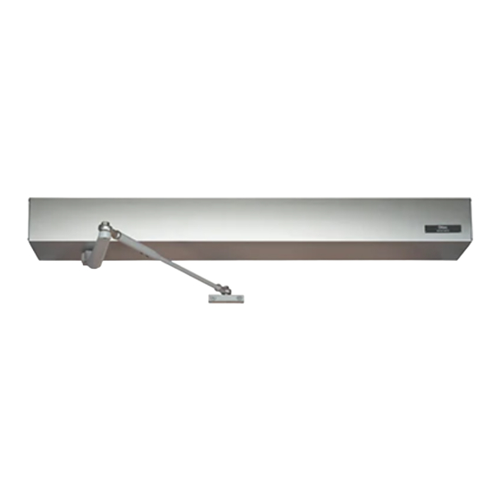
- Page 1 Record HA8-LP Low Energy Door Operator Mechanical Setup – Quick Start Guide...
- Page 2 HA8-LP Low-Energy Swing Door Operator Recommended Tools Item Description Item No. Description Allen Wrench Set Flat Screwdriver, Philip Screwdriver, 5/16” Hex. Nut Driver Power Drill and Drill Bits Additional Fasteners Depending on Surface Level Shims Tape Measure Hand Saw/Power Saw...
- Page 3 HA8-LP Handing Chart...
- Page 4 Installation of the Back Plate Step 1) Remove motor/ gear box and controller from back plate Step 2) Position Back Plate above door and onto the frame. Notes: vertical position • push arm application - flush with • bottom of frame. pull application - 1.375”...
- Page 5 Installation of the Back Plate Step 4) Ensure Back Plate is positioned level and complete the fastening to frame and wall. See Figure 4 Figure 4 Step 5) Fasten Back plate to door jamb and wall using three fasteners per side as shown in figure 5 Figure 5 Step 6) Shims provided by installer shown...
- Page 6 Installation of Power and Motor/Gearbox Step 7) Use the pre drilled holes in the back plate to locate and pull the 120vac building power supply through. Step 8) Attach supplied Splined spindle to gear box. Use ¼-20 socket screw to fasten spindle to output shaft.
-
Page 7: Installation Of Control Board
Installation of Control Board Step 10) Position the control board on to the back plate and fasten using the provided four screws. Step 11) With power off, connect the building power to the control board using two wire nuts to secure. - Page 8 Installation of Push Arm Step 13) Open door to desired opening degree Cut Rod to Length 14” Step 14) With door open measure over from edge of door 14” and arm parallel to bottom of jamb, Arm Shoe Door Shown Open mark shoe holes onto door.
- Page 9 Installation of Push Arm Step 16) Setting Pre-load Door Shown Open Remove Arm from output shaft Toggle hold open button on end cap Verify that pinion output shaft turns in the right direction When spindle stops, open the door and connect main arm to spindle output shaft and tighten Turn hold open off Door should close and latch the door...
- Page 10 Installation of Pull Arm Step 17) Pull Arm Door Shown Open Toggle hold open button on end cap Verify that pinion output shaft turns in the right direction Figure 12 When spindle stops, open the door and connect main arm to spindle output shaft and tighten.
- Page 11 Signage Install all safety, traffic control, and instruction decals to the door as required. This is very important. Failure to do this leaves the installer LIABLE for any accident that might occur. This must be done! A summary of the ANSI standard 156.19 requirements for safety decals is as follows: Each decal shall be mounted on the door at a height of 58 ±...
- Page 12 Mechanical Installation Complete Next Step - See Control Board Setup...
Need help?
Do you have a question about the HA8-LP and is the answer not in the manual?
Questions and answers