Table of Contents
Advertisement
INTRODUCTION
Preface
This document is valid for the harmony series EV Charger.
This document is valid for the harmony series EV Charger.
The pictured devices used in this document are visual examples. The figures and explanations contained in
The pictured devices used in this document are visual examples. The figures and explanations contained in
The pictured devices used in this document are visual examples. The figures and explanations contained in
this document refer to a typical device design. The devices used by you may differ in their appearance
this document refer to a typical device design.
We recommend always keeping the charging station updated to the most recent software version, as this
We recommend always keeping the charging station updated to the most recent software version, as this
We recommend always keeping the charging station updated to the most recent software version, as this
contains functional enhancements and product improvement.
contains functional enhancements and product improvement.
Purpose of this Guide
The document describes the user guide for harmony series EV Charger.
scribes the user guide for harmony series EV Charger.
User Manual for Harmony Series EV Charger
User Manual for Harmony Series EV Charger
The devices used by you may differ in their appearance
Advertisement
Table of Contents

Subscribe to Our Youtube Channel
Related Manuals for EXICOM POWER SOLUTIONS Harmony Series


Summary of Contents for EXICOM POWER SOLUTIONS Harmony Series
- Page 1 We recommend always keeping the charging station updated to the most recent software version, as this contains functional enhancements and product improvement. contains functional enhancements and product improvement. Purpose of this Guide The document describes the user guide for harmony series EV Charger. scribes the user guide for harmony series EV Charger.
-
Page 2: Representation Of Safety Instructions
SAFETY MEASURES AND INSTRUCTIONS Harmony series EV Charger complies with IEC 61851 Harmony series EV Charger complies with IEC 61851-1, Safety Standard. All the components used in the 1, Safety Standard. All the components used in the charger are certified. The charger complied with all the norms as per the safety standard. For user safety, charger are certified. -
Page 3: Prohibited Areas
Prohibited Areas Any non-company’s technical personnel or non-company's authorized technical personnel do not open the cover, otherwise, you will have the risk of electric shock, and lose the warranty qualification. Safety Precautions Make sure that the equipment is well-grounded to avoid electric shock before opening the equipment. -
Page 4: Required Tools
Required Tools Multimeter, Clamp meter. SD Card, U-Drive. USB-RS232 serial tool, USB-UART serial tool. LAN Cable, IXXAT CAN Converter, LAPTOP. - Page 5 ABBREVIATIONS While reading this documents you might see few abbreviations as mentioned below, S. No Abbreviations Full Forms EVSE Electric vehicle supply equipment EVDC Electric vehicle direct current EVAC Electric vehicle alternating current Electric Vehicle Ampere Ampere hour Miniature Circuit Breaker MCCB Molded Case Circuit Breaker Comm.
- Page 6 Combined Charging System CHAdeMO Charge de Move Batt. Battery Universal Serial Bus Voltage Alternating current Voltage Direct Current...
-
Page 7: Product Overview
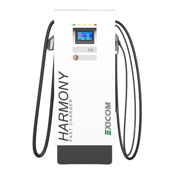
PRODUCT OVERVIEW Harmony – Fast charger solution is Exicom’s most innovative design and a true representation of interoperability. The system has three connectors - CCS, CHAdeMO& AC TYPE 2: 142kW (DC: 120kW + AC: 22kW). All three gun’s cab used at the same time for charging three vehicles at the same time. Technical details are explained below, Dimensional Information Below given is the system dimensional information for harmony system,... -
Page 8: System Architecture
ii) 180 kW iii) 240 kW System Architecture Harmony – Fast charger solution is Exicom’s most innovative design and a true representation of interoperability. The system has three connectors - CCS, CHAdeMO& AC TYPE 2: 142kW (DC: 120kW + AC: 22kW). All guns can be used in Parallel for charging. - Page 9 Key Operated Lock Housing Cover LED Bar LCD Display RFID Reader Emergency Switch Cable Gland Charging Cable Charging Gun Plug SMR’s Cover Charging Gun Dummy Socket Ventilation...
-
Page 10: Technical Specifications
Technical Specifications Parameters 60 kW 82 kW 120 kW 142 kW 142 kW Power Input Input Voltage 415 VAC, 3 Phase/ L1, L2, L3, N, PE Input Voltage 320VAC to 520VAC Range Input Frequency 45Hz - 55Hz Range < 5 % Power Factor >... - Page 11 User Interface and Display 7" LCD Touch Screen control Support Language English Emergency Switch Available (Mushroom red switch) Charging operation Cyclic Charge Option Auto Charge, Mode Selection (Time/Power/SOC) Visual Indication Presence of supply, State of Charging, Error User RFID/APP/OTP/QR (as per requirement) Authentication Communication EVSE and EVCC...
-
Page 12: Key Features
Mechanical IP Rating IP 54 Forced air cooling Cooling Dimension (H 1850x715 1850x715 x W x D) (mm) .4x633 .4x746.7 ~1850x650x513 Charging Cable length >4.5 meter (standard) Interface 7" Touch Screen LCD ARAI Available Certifications IEC61851 Available Available *The system is available with both configuration i.e. single and dual gun. **The change in dimensions as per Exicom’s latest design. - Page 13 Output configurations & Protocols Same system cabinet is designed to support all types of protocol standards available with maximum up to three guns. The output configurations are explained below, Protocol Combinations 60 kW 82 kW 120 kW 142 kW 180 kW 240 kW CCS 2 + CHAdeMO + Type 2 ...
- Page 14 EVSE to EVCC Communication Protocols Charging Standards Applicable protocols CCS 2 PLC in CCS 2 (DIN 70121 & ISO 15118) GB/T CAN in GB/T 27930 CHAdeMO CAN in CHAdeMO v 1.2 Rectifier/SMR Module EV series high efficient rectifier/SMR modules are designed to convert AC mains to regulated DC for powering electric vehicles.
- Page 15 SMR LED Indications Normal Indicator Light Abnormal State Cause of Abnormality State Input power not available Operation indicator Light(Green) Flash Communicating with the system’s controller AC input overvoltage, Internal over- temperature,Abnormal bus voltage(self- Alarm indicator recoveryif alarm is cleared) Light(Yellow) Communication failed with system’s Flash controller...
-
Page 16: Controller Card
Controller Card The combination of pilot controller and upper controller card is heart of the EV charger and it controls the system’s overall functionalities. The backend OCPP server communication and user interface display is controlled by the upper controller whereas the CCS, CHAdeMO, GBT and AC type 2 charging communication is controlled by the pilot controller card. -
Page 17: Installation Instructions
INSTALLATION INSTRUCTIONS The Harmony series EV chargers are designed to be installed on the floor. The correct site survey is to be done before installation the charger at any location. Proper installation is absolutely necessary and to be conducted as per the below details,... -
Page 18: Site Selection Criteria
Site Selection Criteria The charging station was constructed for the indoor and outdoor area. Accordingly, it is necessary to ensure the correct set-up requirements and the protection of the device at the installation site. The following criteria must be taken into account when selecting a location, ... - Page 19 Input Power & Cable and MCB/MCCB requirements Sr no Item Specifications AC Supply System 3-Phase, 5 Wire AC system (3Ph+N+E) Nominal Input voltage 3Ø, 415VAC (Range: 320VAC to 520VAC) Input Frequency 50Hz Input Power 70KVA-160KVA (As per the System Capacity) Neutral to earth Voltage <1.0 VAC Sr no...
- Page 20 EV Charger Installation details The Charger is designed to be installed on the floor. The below pictures from figure No. 2-A to figure No. 2-O will guide for the foundation to be prepared for charger and installations of charger on that foundation, 60, 82, 120 and 142 kW *Foundationsizemayvaryaspersite...
- Page 21 Fig No. 2-C: Foundation Floor Top View Fig No. 2-D: Charger bottom view (Grouting details and cable inlet position)
- Page 22 (ii)180 kW *Foundationsizemayvaryaspersite requirement orselection. Fig No. 2-E: Front View Fig No. 2-F: Rear View Fig No. 2-G: Foundation Floor Top View...
- Page 23 Fig No. 2-H: Charger bottom view (Grouting details and cable inlet position) (iii)240 kW *Foundationsizemayvaryaspersite requirement orselection. Fig No. 2-I: Front View Fig No. 2- J: Rear View...
- Page 24 Fig No. 2-K: Foundation Floor Top View Fig No. 2-L: Charger bottom view (Grouting details and cable inlet position)
- Page 25 Common for Harmony series systems Fig No. 2-M: Foundation Floor Rear View Fig No. 2-O: Charger Fig No. 2-N: Cable Inlet in the Foundation Mounting method...
- Page 26 EV Charger Connection The charger works on three phase 5 wires system. So, as per charger rating the input cable with distribution box is to be installed (refer Annexure-I for ratings). Below given is the block diagram view for the same, Fig No.
- Page 27 Rectifier Installation Gently insert the Rectifier in the Rectifier slot to ensure proper connectivity with the connector. Insert methods are as given in fig No. 4-A & fig No. 4-B w.r.t the rectifier Type. Once Rectifier is inserted properly, rectifier will get registered automatically, if power Input is available.
-
Page 28: Commisioning Instructions
COMMISIONING INSTRUCTIONS EV Charger Commissioning Service is a key part of an overall deployment of the EV Charging Station. This service provides the certified Exicom field service Engineers needed to activate and check the functionality of the system. Exicom will send a technician to verify proper connection and functionality of the charging station following installation by the contractor. - Page 29 Normal Abnormal Indicator Light State State Cause of Abnormality Operation Input power not available indicator Light (Green) Flash Communicating with the system’s controller Alarm indicator AC input overvoltage, Internal overtemperature, Light (Yellow) Abnormal bus voltage (selfrecovery if alarm is cleared) Flash Communication failed with system’s controller Fault indicator...
- Page 30 QUICK/BASIC SETTING NAVIGATION QUICK/BASIC SETTING NAVIGATION Check active alarms, Home > > Active Alarm Check history logs, Home > > Chnages Alarm Check software version upper controller, Home > > About Check software version of pilot controller, Home >> Password > Param set > CCU Specific Setting > CCU Firmware version Set Date and time, Home >>...
- Page 31 Set Charge point Model , Home >> Password > Param set > Charge point boot info > Charge point Model Set Charge point Serial number Home >> Password > Param set > Charge point boot info > Charge point SN Set OCPP URL address , Home >>...
- Page 32 CHARGE FLOW Introduction Harmony EVDC Series Charger sanctions users to utilize an RFID Card/ OTP/ QR Code to initiate the charging. For OTP and QR Code specific charging, charger should be connected to OCPP Server. The charger supports all three guns charging at the same time. Below is a detailed description of every step that a user can follow for a successful charging attempt.
- Page 33 Single Gun harmony charger’s home screen, Two Gun harmony charger’s home screen,...
- Page 34 Three Gun harmony charger’s home screen, SIM Network OCPP Server & Internet Connectivity Availability...
-
Page 35: Authentication Methods
Authentication Methods The charger supports various options/methods of user authorization. All these options are as below, The charger supports various options/methods of user authorization. All these options are as below, The charger supports various options/methods of user authorization. All these options are as below, Click and scan RFID card on charger at RFID Click and scan RFID card on charger at RFID symbol as below,... -
Page 36: Charging Modes
Charging Modes The charger support various options/methods for charging modes. All these options are as below, Mode Description Reference AUTO This mode fully (100%) charge vehicle unless the charging stopped by fault/vehicle TIME This mode allows to charge vehicle for a specific duration of time. - Page 37 GUN-A charging procedure Below steps are to be followed to start/stop charging on GUN-A InsertGun-Atothevehiclesocket.Ifthegunispluggedinproperly,the“Connect”buttonofDC-1 willbecomesactive.Referpicturebelow Press“Connect”button,thechargerasksforuserauthentication.Fordetails,refer “Authentication Methods” Post successful authorization, the charger asks for charge mode selection, select suitable charging mode. For details, refer “Charging Modes” of this section...
- Page 38 Wait while “Preparing” as the charger is establishing communication link with Vehicle After successful connection with vehicle,the charging starts and related parameter sonscreen will be displayed.
- Page 39 Stop of charging Press“CANCEL”and swipe same RFID card to stop charging OR The charging will be stopped automatically once charging mode condition satisfied. After stop of charging, summary screen will be displayed. GUN-B charging procedure Below steps are to be followed to start/stop charging on GUN-B, ...
- Page 40 Press“Connect” button, the charger asks for user authentication. For details, refer“ Authentication Methods”of this section. Post successful authorization, the charger asks for charge mode selection, select suitable charging mode. For details, refer “Charging Modes” of this section.
- Page 41 Wait while“Preparing”as the charger is establishing communication link with Vehicle. After successful connection with vehicle, the charging starts and related parameters on screen will be displayed.
- Page 42 Stop of charging Press“CANCEL”and swipe same RFID card to stop chargingOR The charging will be stopped automatically once charging mode condition satisfied. After stop of charging, summary screen will be displayed.
- Page 43 GUN-C charging procedure Below steps are to be followed to start/stop charging on GUN-C, Insert Gun-C to the vehicle socket. If the gun is plugged in properly, the “Connect” button of AC will becomes active. Refer picture below, Press“Connect”button, the charger asks for user authentication. For details, refer“Authentication Methods”of this section.
- Page 44 Post successful authorization, the charger asks for charge mode selection, select suitable charging mode. For details, refer “Charging Modes” of this section. Note: As the Type 2 vehicle do not send SOC to charger, so SOC mode for 3rd gun is not provided. ...
- Page 45 After successful connection with vehicle, the charging starts and related parameters on screen will be displayed. Stop of charging Press“CANCEL”and swipe same RFID card to stop chargingOR The charging will be stopped automatically once charging mode condition satisfied. ...
- Page 46 TROUBLESHOOTING INTRUCTIONS During charging vehicle requests for voltage & current and charger delivers the same by limiting the current as per requested current. However, charging may be stopped/interrupted by varies reasons. Charging can be stopped by-charger, vehicle or by any other means. Charger generates stop reason based on the nature of charging stops.
- Page 47 1. Check wires of 10-J30 connectors for respective gun. 2. Check if rectifiers are building the voltage. Alarm is Abnormal volt of 3. Check if DC contactors of respective guns are reported by outside bus working OK. Charger 4. Re-calibrate the device. 5.
- Page 48 1. Check battery voltage after contractors (Vehicle end). If no voltage, please inform the vehicle manufacturer. Alarm is EV Relay pull-in reported by timeout 2. Change vehicle and test again. Charger 3. Take CAN logs of a respective gun and share it for analysis.
- Page 49 1. Check if the gun is properly connected to the vehicle. 2. Restart the vehicle and try charging again. 3. Check 12V between CP & PE on PLC board when gun not connected, 9V when the gun is connected Alarm is and 6V when charging.
- Page 50 1. Check SMR CAN wiring. 2. Check if all SMR are inserted properly. Alarm is 3. Check if input MCCB is ON & input voltage is All Rectifier fail reported by healthy. Charger 4. Open the cover and check SMR red LED, if RED LED is ON, remove one SMR and check individually.
- Page 51 Alarm is AC connector PWM connection failure. Please PWM Failure reported by check the AC connector cable. Charger The earth is not properly connected. Please check the system wiring. Alarm is Ground Fault reported by Detected Charger 1. Please check if RFID is ON/OFF. Alarm is CR Comm Fail reported by...
- Page 52 Charging stopped/Interrupted by Vehicle Alarm Name Alarm Alarm Alarm Resolution Code Cause 1. Please change the vehicle and try again charging. 2. Inform the user to check at the vehicle end. Alarm is EV Request 3. Please take serial data & CAN1/CAN2 data of PLC reported Stop module.
- Page 53 1. Please change the vehicle and try again charging. Battery 2. Inform the user to check at the vehicle end. Alarm is voltage 3. Please take serial data & CAN1/CAN2 data of PLC reported deviation module. Also capture SMR data from controller's by Vehicle error CAN3 Port.
- Page 54 1. At HLC stages, communication fails. 2. Please change the vehicle and try again charging. High- Alarm is 3. Inform the user to check at the vehicle end. Level Comm reported 4. Please take serial data & CAN1/CAN2 data of PLC Fail by Vehicle module.
- Page 55 Charging stopped/interrupted– Other reasons Alarm Alarm Name Alarm Cause Alarm Resolution Code Alarm is cause Local Stop User Canceled the charging from display. by User Charging stopped from the OCPP server via the Alarm is cause Server Stop "Remote stop" command. Please check with the OCPP by User server engineer.
-
Page 56: Alarms Troubleshooting
Alarms Troubleshooting The chargers are equipped with multiple devices such as rectifier’s module, MCBs, energy meters & controllers, etc. These devices communicate with the main controller board. This master control board controls the charger and if anything unusual happens the charger generates the alarm. All types of alarms and their explanation is explained below, System-Level Alarms These are system-level alarms,... - Page 57 GUN-A Alarms These alarms are related to GUN-A, Alarm Name Alarm Cause Alarm Resolution 1.This is only for the GBT connector. 2. Please check the connector e-lock configuration E-Lock Failed - Locking of Gun-A in display. Group A failed. 3. Check 12V pulse for LKA+ & LKA-. 4.
- Page 58 GUN-B Alarms These alarms are related to GUN-B, Alarm Name Alarm Cause Alarm Resolution 1.This is only for the GBT connector. 2. Please check the connector e-lock configuration E-Lock Failed - Locking of Gun-B in display. Group B failed. 3. Check 12V pulse for LKA+ & LKA-. 4.
- Page 59 GUN-C Alarms These alarms are related to GUN-C Alarm Name Alarm Cause Alarm Resolution 1.Check input voltage with multimeter AC Fail Alarm AC input is failed. GUN - C 2.Check if input RCD is OFF.
-
Page 60: System Schematic Diagram
SYSTEM SCHEMATIC DIAGRAM The harmony series chargers are available in single gun, two gun and three gun configuration. Below are schematic diagram for all three types of systems, Single GUN configuration... - Page 61 Two GUN configuration...
- Page 62 Three GUN configuration...
- Page 63 ANNEXURE-I Input Cable, LUG & MCB/MCCB Selection table for cable length maximum up to 25 meters S.No Description Cable size Copper Lugs MCB/MCCB 4CX16 sq-mm(R,Y,B,N) Ring type Lugs 16 sq-mm, M8 EVDC 15 kW- 63A, 4P MCB DC001 (1G) 1CX 16 sq-mm (PE) Ring 16 sq-mm, M8 4CX16 sq-mm (R,Y,B,N) Ring type Lugs 16 sq-mm, M8...
- Page 64 4Cx120 sq-mm Ring type lug 120 sq-mm, M8 EVDC 142 (R,Y,B,N) 400A, 4P kW Wall-box MCCB (3G) 1CX 35 sq-mm (PE) Ring type lug 35 sq-mm M8 4Cx150 sq-mm Ring type lug 150 sq-mm. M8 EVDC 150 (R,Y,B,N) 400A, 4P kW Wall- MCCB box(2G)
- Page 65 ANNEXURE-II Rectifier/SMR 30kW/20kW modules are to be configured as per system requirement. Below is the procedure to set the DIP switches for the same. Inside EV charger, rectifier/SMR magazine is provided with 2 sections i.e. upper and lower. According to the sections, the setting of the DIP switch for rectifiers are to done.
Need help?
Do you have a question about the Harmony Series and is the answer not in the manual?
Questions and answers
Location of SPD device in 120 kw harmony charger
The SPD (Surge Protection Device) is integrated into the EV chargers of the Harmony Series, including the 120 kW charger. It is a Class C SPD that provides protection against sudden voltage impulses by grounding any voltage above its rated capacity. However, the exact physical location of the SPD within the charger is not specified in the available information.
This answer is automatically generated