Carrier 40UV Installation, Start-Up And Service Instructions Manual
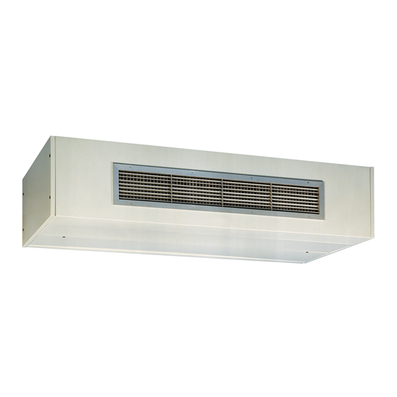
Floor and ceiling mounted unit ventilators
Hide thumbs
Also See for 40UV:
Table of Contents
Advertisement
Installation, Start-Up and Service Instructions
CONTENTS
SAFETY CONSIDERATIONS . . . . . . . . . . . . . . . . . . . 1
INTRODUCTION . . . . . . . . . . . . . . . . . . . . . . . . . . . . . . 3
PRE-INSTALLATION . . . . . . . . . . . . . . . . . . . . . . . . . . 3
Unpack and Inspect Units . . . . . . . . . . . . . . . . . . . . . 3
Protect Units from Damage . . . . . . . . . . . . . . . . . . . . 3
Prepare Jobsite for Unit Installation . . . . . . . . . . . . . 3
Identify and Prepare Units . . . . . . . . . . . . . . . . . . . . . 3
Drainage . . . . . . . . . . . . . . . . . . . . . . . . . . . . . . . . . . . . 3
INSTALLATION . . . . . . . . . . . . . . . . . . . . . . . . . . . . . . 5
Step 1 - Place Units in Position . . . . . . . . . . . . . . . . 5
Step 2 - Make Piping Connections . . . . . . . . . . . . 10
Piping Insulation . . . . . . . . . . . . . . . . . . . . . . . . . . . . 16
Step 3 - Make Electrical Connections . . . . . . . . . . 16
PRE-START-UP . . . . . . . . . . . . . . . . . . . . . . . . . . . . . 18
Pre-start Checks . . . . . . . . . . . . . . . . . . . . . . . . . . . . 18
START-UP . . . . . . . . . . . . . . . . . . . . . . . . . . . . . . . . . 18
OPERATION . . . . . . . . . . . . . . . . . . . . . . . . . . . . . . . . 18
Freeze Stat (Optional) . . . . . . . . . . . . . . . . . . . . . . . . 18
CONTROLS . . . . . . . . . . . . . . . . . . . . . . . . . . . . . . . . 18
Chilled Water with Valve Control . . . . . . . . . . . . . . . 18
Chilled Water with Face and Bypass Control . . . . . 18
Direct Expansion (DX) Cooling Control . . . . . . . . . 19
Hot Water or Steam with Valve Control . . . . . . . . . 19
Hot Water with Face and Bypass Control . . . . . . . . 19
Control . . . . . . . . . . . . . . . . . . . . . . . . . . . . . . . . . . 19
Bypass Control . . . . . . . . . . . . . . . . . . . . . . . . . . . 19
2-Position Control Valves . . . . . . . . . . . . . . . . . . . . . 19
Condensate Pump (Optional) . . . . . . . . . . . . . . . . . . 19
Condensate Pan Float Switch (Optional) . . . . . . . . 19
SERVICE . . . . . . . . . . . . . . . . . . . . . . . . . . . . . . . . . . 19
Manufacturer reserves the right to discontinue, or change at any time, specifications or designs without notice and without incurring obligations.
Catalog No. 04-53400052-01
Part No. 5H1060560000
Page
Printed in U.S.A.
Form 40UV-UH-12SI
Floor and Ceiling Mounted
Unit Ventilators
Maintenance . . . . . . . . . . . . . . . . . . . . . . . . . . . . . . . .19
Access . . . . . . . . . . . . . . . . . . . . . . . . . . . . . . . . . . . .19
Maintenance Schedule . . . . . . . . . . . . . . . . . . . . . . .22
REPLACEMENT PARTS . . . . . . . . . . . . . . . . . . . . . .25
UNIT START-UP CHECKLIST. . . . . . . . . . . . . . . . .CL-1
SAFETY CONSIDERATIONS
Installation and servicing of air-conditioning equipment can be
hazardous due to system pressure and electrical components. Only
trained and qualified service personnel should install, repair, or
service air-conditioning equipment.
Untrained personnel can perform basic maintenance functions of
cleaning coils and filters and replacing filters. All other operations
should be performed by trained service personnel. When working
on air-conditioning equipment, observe precautions in the
literature, tags and labels attached to the unit, and other safety
precautions that may apply.
Follow all safety codes. Wear safety glasses and work gloves. Use
quenching cloth for unbrazing operations. Have fire extinguisher
available for all brazing operations.
It is important to recognize safety information. This is the
safety-alert symbol
. When you see this symbol on the unit and
in instructions or manuals, be alert to the potential for personal
injury.
Understand the signal words DANGER, WARNING, CAUTION,
and NOTE. These words are used with the safety-alert symbol.
DANGER identifies the most serious hazards which will result in
severe personal injury or death. WARNING signifies hazards
which could result in personal injury or death. CAUTION is used
to identify unsafe practices, which may result in minor personal
injury or product and property damage. NOTE is used to highlight
suggestions which will result in enhanced installation, reliability,
or operation.
IMPORTANT: The use of this manual is specifically intended
for a qualified installation and service agency. A qualified instal-
lation and service agency must perform all installation and ser-
vice of these appliances.
Units with DX evaporator coils contain the refrigerant R-410A.
Review the R-410A Material Safety Data Sheet (MSDS) for
hazards and first aid measures.
Refrigerant charging should only be carried out by an
EPA-certified air conditioning contractor.
WARNING
Before performing service or maintenance operations, turn off
main power switch to the unit. Electrical shock could cause
personal injury.
Pg 1
40UV,UH
2-23
Replaces: 40UV-UH-11SI
Advertisement
Table of Contents

Related Manuals for Carrier 40UV


Summary of Contents for Carrier 40UV
-
Page 1: Table Of Contents
SERVICE ........19 Manufacturer reserves the right to discontinue, or change at any time, specifications or designs without notice and without incurring obligations. Catalog No. 04-53400052-01 Printed in U.S.A. Form 40UV-UH-12SI Pg 1 2-23 Replaces: 40UV-UH-11SI... - Page 2 WARNING CAUTION Improper installation, adjustment, alteration, service or main- Ensure that the supply voltage to the appliance, as indi- tenance can cause property damage, injury or death, and could cated on the serial plate, is not 5% less than the rated volt- cause exposure to substances which have been determined by age.
-
Page 3: Introduction
This document contains general installation instructions for the complete sample installation in a typical room at jobsite. Check all 40UV, UH unit ventilators. Refer to the unit wiring diagram or to critical dimensions such as pipe, wire, and duct connection specific manufacturer literature for any other type of requirements. - Page 4 Table 1 — Physical Data UNIT 40UV, UH 0750 1000 1250 1500 NOMINAL AIRFLOW (cfm) 0750 1000 1250 1500 UNIT OPERATING WEIGHT Floor Mounted, 16-5/8 in. Units (lbs) Floor Mounted, 21-7/8 in. Units (lbs) Ceiling Mounted Units (lbs) SUPPLY FANS...
-
Page 5: Installation
INSTALLATION CEILING MOUNTED UNITS The instructions detailed below are for the Installation of a Stan- dard unit. Accommodations and adjustments will be required for CAUTION the usage of additional unit accessories. Should assistance be required for the installation of these additional items, contact the Units must be installed level and plumb. - Page 6 DIMENSIONS (in.) UNIT AIRFLOW 40UV (cfm) 0750 1000 1000 1250 1250 1500 1500 Fig. 4 — 40UV Dimensions — 16-5/8 in. Depth — Floor Mounted Units (Standard)
- Page 7 DIMENSIONS (in.) UNIT AIRFLOW 40UV (cfm) 0750 1000 1000 1250 1250 1500 1500 Fig. 5 — 40UV Dimensions — 21-7/8 in. Depth —Floor Mounted Units...
- Page 8 DIMENSIONS UNIT AIRFLOW (in.) 40UH (cfm) 0750 1000 1000 1250 1250 1500 1500 Fig. 6 — 40UH Dimensions — Front Discharge — Ceiling Mounted Units...
- Page 9 DIMENSIONS UNIT AIRFLOW (in.) 40UH (cfm) 0750 1000 1000 1250 1250 1500 1500 Fig. 7 — 40UH Dimensions —Down Discharge — Ceiling Mounted Units...
-
Page 10: Step 2 - Make Piping Connections
Step 2 — Make Piping Connections LEFT HAND CONNECTIONS RIGHT HAND CONNECTIONS Piping installation is described in the following sections on pages 10-16 and illustrated in Fig. 8-29. AIR FLOW AIR FLOW CHILLED/HOT WATER COILS (NO PIPING PACKAGE) CAUTION Units not approved for use in potable water systems. Hot water supplied to the hot water heating option must not exceed 200°F temperature or 125 psig pressure. -
Page 11: Chilled/Hot Water Coils (Piping Package)
Table 4 — Piping Location Dimensions Table 6 — Hot Water Re-Heat Coil Piping Locations (Chilled Water Pre-Heat Coil) UNIT DIMENSIONS (in.) UNIT DIMENSIONS (in.) COIL COIL DEPTH DEPTH ROWS (in.) (in.) 1-row 17.50 8.75 10.25 2.25 16.75 9.50 11.50 1.25 2-row 17.50 8.75 10.50 2.25 16.50 9.50 11.50 1.50 16-5/8 16-5/8... -
Page 12: Direct Expansion (Dx) Coils (No Piping Package)
NOTE: Condensate drain connection located in right end compartment. Fig. 15 — Chilled Water Coil with Pre-Heat Coil (With Piping Package) NOTE: Condensate drain connection located in right end compartment when unit is equipped with a cooling coil. Fig. 17 — Chilled Water/DX Cooling Coil With Hot Water Re-Heat Coil (With Piping Package) DIRECT EXPANSION... - Page 13 LEFT HAND CONNECTIONS RIGHT HAND CONNECTIONS LEFT HAND CONNECTIONS RIGHT HAND CONNECTIONS AIR FLOW AIR FLOW AIR FLOW AIR FLOW 13.49 13.04 10.16 7.50 13.74 COND. COND. 3.37 DRAIN DRAIN 3.37 10.93 8.86 8.17 LL = Liquid Line COND. COND. 3.37 DRAIN DRAIN...
-
Page 14: Direct Expansion (Dx) Coils (Piping Package)
DIRECT EXPANSION (DX) COILS (PIPING PACKAGE) Unit Size 0750 NOTE(S): 1.For dimensions C and D refer to DX Cooling (Size 0750) with or Unit Size 1000 / 1250 / 1500 without Optional Re-heat Coil Table on page 30. NOTE(S): 2.Condensate drain connection located in right end compartment. 1.For dimensions C and D refer to DX Cooling (Size 1000-1500) with or Fig. -
Page 15: Steam Coils (No Piping Package)
STEAM COILS (NO PIPING PACKAGE) LEFT HAND CONNECTIONS RIGHT HAND CONNECTIONS CAUTION AIR FLOW AIR FLOW Do not operate the units within steam pressure greater than 10 psig. Steam pressure must be 10 psig or lower to avoid ex- cessive discharge air temperatures that could cause burns or personal injury. -
Page 16: Steam Coils (Piping Package)
STEAM COILS (PIPING PACKAGE) NOTE: For units with piping package, not available on Ceiling Mounted units. Chilled water piping package will not be insulated except when piping is routed through pipe tunnel. Chilled water piping package shall be positioned over drain pans to catch con- densate that forms on piping. -
Page 17: Terminal Strip Connections
TERMINAL STRIP CONNECTIONS The terminal strip connections are designed to clamp down on the wires. To properly connect the wires to the terminal strip: Push a small flat-head screwdriver into the square hole on the terminal. Press firmly until the screwdriver hits the back stop and opens the terminal (see Fig. -
Page 18: Pre-Start-Up
PRE-START-UP DX Cooling models only: Shut unit down and disconnect the main power. The compressor NOTE: Refer to start-up sheets. signal Y1 (disconnected from the indoor unit in Step 2) can now IMPORTANT: Start-up and adjustment procedures should be re-connected and main power applied to the system. be performed by a qualified service agency. -
Page 19: Direct Expansion (Dx) Cooling Control
NOTE: Controls sequence is a factory recommendation; when that are required. Consult Carrier for assistance. units are ordered with field installed controls by others or DDC Ready it is up to the installing contractor to fulfill the controls se- The use of torque screwdrivers on panel, cover or component quence that is required. - Page 20 CONTROL PANEL BLOWER MOTOR FREEZE STAT (OPTIONAL) FACE AND BYPASS DAMPER ACTUATOR (OPTIONAL) FIELD INSTALLED PIPING OUTSIDE AIR/RETURN AIR FACE AND BYPASS FILTERS BLOWERS ELECTRICAL BOX WITH POWER DAMPER ACTUATOR DAMPER CONNECTION, DISCONNECT SWITCH AND (OPTIONAL) (OPTIONAL) 3-SPEED FAN SWITCH Fig.
- Page 21 PIPING TOP ACCESS PANELS BASE ASSEMBLY DAMPER ASSEMBLY CONTROL PANEL FILTER COIL ASSEMBLY BLOWER ASSEMBLY PANELS BOTTOM ACCESS PANELS DISCHARGE AIR PANEL ASSEMBLY Fig. 33 — Component Layout Ceiling Mounted Units (Exploded View)
-
Page 22: Maintenance Schedule
Maintenance Schedule NOTE: Refer to Table 13 for troubleshooting. Monthly: • With the Disconnect in the “OFF” position: check the fil- ter(s) and replace if necessary. Slide the filter(s) out of the track and replace with new filter(s). Refer to Fig. 34-35. The filters are positioned under the coil assembly. - Page 23 Table 13 — Troubleshooting Trouble Possible Cause Possible Remedy Unit mounted disconnect in the “OFF” position. Turn the disconnect switch to the “ON” position. Unit mounted 3-speed selector switch in the “0” Turn the 3-speed selector switch to the “1, 2, or 3” position (if equipped with a 4-position switch).
- Page 24 Table 13 — Troubleshooting (cont) Trouble Possible Cause Possible Remedy Measure unit operating pressures. Add charge and Low refrigeration charge. check for leaks. Clogged filter(s). Replace filter(s) as necessary. Replace drier with a direct replacement. DX Split Units Only: Low Suction Clogged liquid line filter drier.
-
Page 25: Replacement Parts
REPLACEMENT PARTS When servicing, repairing or replacing parts on these units, locate the model serial plate on the unit and always give the complete Model Number and Serial Number from the unit see example in Fig. 38. 1500 DeKoven Avenue Racine, WI 53403-2552 VENTILATOR UNIT MADE IN U.S.A. - Page 28 © 2023 Carrier Manufacturer reserves the right to discontinue, or change at any time, specifications or designs without notice and without incurring obligations. Catalog No. 04-53400052-01 Printed in U.S.A. Form 40UV-UH-12SI Pg 28 2-23 Replaces: 40UV-UH-11SI...
- Page 29 UNIT VENTILATOR START-UP SHEET Manufacturer reserves the right to discontinue, or change at any time, specifications or designs without notice and without incurring obligations. Catalog No. 04-53400052-01 Printed in U.S.A. Form 40UV-UH-12SI Pg CL-1 2-23 Replaces: 40UV-UH-11SI...
- Page 30 UNIT VENTILATOR START-UP SHEET (OUTDOOR UNIT) CL-2...
-
Page 31: Unit Start-Up Checklist
ARE THERE ANY LEAKS DETECTED? CONTROLS CHECKLIST: DOES THE UNIT HAVE CARRIER CONTROLS ? IF SO, CONTINUE. CHECK THAT THE UNIT OPERATES PER SEQUENCE OFOPERATION AS STATED IN THE CONTROLLER IOM. RECORD THE THERMOSTAT READINGS IN TABLE BELOW. - Page 32 © 2023 Carrier Manufacturer reserves the right to discontinue, or change at any time, specifications or designs without notice and without incurring obligations. Catalog No. 04-53400052-01 Printed in U.S.A. Form 40UV-UH-12SI Pg CL-4 2-23 Replaces: 40UV-UH-11SI...
Need help?
Do you have a question about the 40UV and is the answer not in the manual?
Questions and answers