Table of Contents
Advertisement
Advertisement
Table of Contents

Related Manuals for E-Seek M500


Summary of Contents for E-Seek M500
- Page 1 M500 User Manual and Programmer SDK Revision 1P Doc No 560802-1A May 19, 2017...
- Page 2 E-Seek reserve the right to make changes to any product to improve reliability, function or design. E-Seek do not assume any product liability arising out of, or in connection with, the application or use of the product, circuit or application described herein.
-
Page 3: Table Of Contents
M500 USER MANUAL AND PROGRAMMER SDK ABLE OF ONTENTS INTRODUCTION ............................. 4 ............................4 RODUCT EATURE ..............................4 REREQUISITE DEVICE DESCRIPTION ............................. 4 M500 ..........................5 VERVIEW OF ODEL ............................ 6 RODUCT PECIFICATION ............................6 ECHNICAL ETAILS ............................7 NPACKING EVICE 2.4.1... - Page 4 M500 USER MANUAL AND PROGRAMMER SDK Page 3...
-
Page 5: Introduction
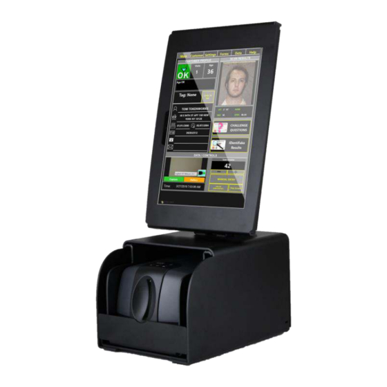
EVICE ESCRIPTION The E-Seek Model M500 Forensic Reader introduces a new performance standard for ID card reading and authentication. It extracts hidden security features of a drivers' license, Military ID or any identity card for authentication purposes in addition to reading and decoding the electronic information contained in the barcode or magnetic stripe. -
Page 6: Overview Of Model M500
M500 USER MANUAL AND PROGRAMMER SDK M500 VERVIEW OF ODEL Figures, 1 and 2 illustrate the major modules and components of the M500. Figure 1 Figure 2 Page 5... -
Page 7: Product Specification
Blue and White center mounted LEDs under user control Red LED for Error status Communication High Speed USB 2.0 Weight M500 device: 4.25 lb (Without Power Supply) Dimensions 8.5" Length x 5.7" Width x 4.8" Height Regulatory Complies with FCC & CE rules Power Supply Output 15V DC 2.4 A / Input 100-240V 50-60 Hz... -
Page 8: Unpacking Device
The power cord plugs into the power jack Figure 3 2.4.1 USB C ABLE The M500 is provided with a USB interface cable. This cable allows the M500 to interface with standard USB 2.0 or higher port on your computer. Figure 4 Page 7... -
Page 9: White Balance Calibration Card
M500 USER MANUAL AND PROGRAMMER SDK 2.4.2 HITE BALANCE CALIBRATION CARD Figure 5 The calibration card is used to calibrate the white balance. Calibration could be required after shipping or prolonged use. To perform the white balance calibration simply insert the card with the arrow side first. -
Page 10: Getting Started
Run M500_USB_DRIVER-64.exe WinDriver should appear under Jungo in Device Manager Window. Figure 7 Next, connect M500 Power cable and then USB cable to your host PC. Now the M500 should appears under Jungo in Device Manager Window. Figure 8 Page 9... -
Page 11: Upgrading Firmware
The Demo application checks the M500 firmware version when it starts or the M500 boots. If the firmware in the M500 is not the correct version for this DLL then the demo software will pop up a dialog box with the option of upgrading the firmware. -
Page 12: Running Demo Application
The PC software consists of an application exe, a C# API assembly, and a C/C++ DLL that communicates with the M500 over USB. The PC software also includes a third party USB driver from Jungo. This document covers the M500 C# sample application and the C# API that gives a C# developer a simple interface to the unmanaged C/C++ M500 DLL. -
Page 13: Eject Button
M500 USER MANUAL AND PROGRAMMER SDK JECT UTTON This button, which is located on the top of the units, is used to try to eject a jammed card. 6.3 GUI Figure 9 The GUI has a toolbar and controls on the top, small preview images on the left, a large selectable main image, and a status bar on the bottom. -
Page 14: Small Image Preview Pane
M500 USER MANUAL AND PROGRAMMER SDK 6.3.1 MALL MAGE REVIEW Figure 10 There are seven small panes which display the scanned card using different lighting. The first two images are the front (right) and back (left) images using white light. -
Page 15: Toolbar And Controls
The blue “i” toolbar button opens a modal dialog box with the current version numbers. The “M500” text is green when the USB connection is good and red when the USB connection fails. The “User LED” button toggles the middle user LEDs on the top of the unit. There are a blue LED and a white LED mounted next to each other. -
Page 16: Scan Modes
M500 USER MANUAL AND PROGRAMMER SDK 6.3.3 CAN MODES By default the normal scan mode is RGB-IR-UV. Click on the “Scan Normal” button until it changes to “Scan RGB” for fast RGB only scanning. Page 15... -
Page 17: About Dialog Toolbar Button
Clicking on the blue “i” brings up the about dialog box. Note that the API, DLL, and M500 (firmware) versions are always the same (In this case 1.6). The DLL checks for the expected M500 (firmware) and barcode decoder versions and brings up a dialog box if the versions do not match. -
Page 18: Errors
Whenever the DLL detectcs a firmware version mismatch or other serious error it will sends an error event (In this case EV_ERR_FW_VER) and send a command to the firmware to flash its red LED. On receiving this event the demo application will pop up the following dialog allowing the user to upgrade the M500’s firmware. -
Page 19: Architecture
Microsoft USB drivers M500 firmware The application (M500.exe or user application), M500api.dll, M500dll.dll, and SD2.dll must be in the same directory. The DLL will create a log file (M500dll.log) in the directory in which it is running by default but it can be disabled if needed. -
Page 20: M500 Demo App
M500 DEMO This is the main form and contains the code that interfaces with the M500 C# API. It calls the Init() function which initializes the M500DLL which then creates its own thread to communicate with the M500 and automatically transfer images without using the applications UI thread. -
Page 21: C# Api
Call this function with false before Init() to override the default behavior (as of version 1.9) of automaticaly updating the M500’s firmware if it is out of date. You do not have to call this function if you want the default behavior of automatic firmware upgrade. - Page 22 M500 USER MANUAL AND PROGRAMMER SDK bool LogIn(bool bLogin) When true the unit will scan when a card is inserted (normal operation). When false the unit will not scan when a card is inserted. void UserLED(E_LED eLED) Controls the center LEDs. First generation units only have a blue LED. Second generation units will also have a white LED.
- Page 23 SaveAs(string strFilename) Saves the last scan as a tif file. Open(string strFilename) Refreshes the APIs bitmaps, barcode, and magstripe data from an M500 tif file. bool WrUserData (byte[] aryData) Writes a user data byte array to flash (128 byte limit).
- Page 24 M500 USER MANUAL AND PROGRAMMER SDK Events: The M500 DLL sends event call backs to the application on a thread the M500 DLL creates. EV_MID_SEN Card is at the middle sensor and a scan is about to begin EV_MS_RDY Mag stripe data ready...
-
Page 25: Api Structures
M500 USER MANUAL AND PROGRAMMER SDK 9.2 API S TRUCTURES M500_IMG The C# API class has a bitmap for each of the seven images: class M500_IMG … Bitmap m_RgbFrBmp = Bitmap(XPIXELS, YPIXELS, PixelFormat.Format24bppRgb); Bitmap m_RgbBkBmp = Bitmap(XPIXELS, YPIXELS, PixelFormat.Format24bppRgb); Bitmap m_IrFrBmp Bitmap(XPIXELS, YPIXELS, PixelFormat.Format8bppIndexed);... - Page 26 M500 USER MANUAL AND PROGRAMMER SDK The C# API M500_BC structure contains a 2D data structure. unsafe public struct M500_BC public BC_1D // 1D (linear) public BC_2D // 2D (PDF417) public int iMajor; public int iMinor; public int iOrient; // Orientation public int iTry;...
- Page 27 M500 USER MANUAL AND PROGRAMMER SDK Example pseudo code CM500api m_M500 = CM500api(); // C# API object m_M500.Init(); m_M500.RegCB(OnNewEvent); // Register event callback … // Event callback in DLLs thread public void OnNewEvent(int iEvent) switch (iEvent) case EV_MS_RDY: Invoke(new MethodInvoker(ScanMsRdy));...
-
Page 28: Maintenance
Verification process does NOT re-calibrate the M500. Calibiration Card The cleaning card is designed to clean the internal rollers and the Magnetic Read Head inside the M500. The need for cleaning varies, but is primarily dependent on the usage or the number of card scans. The general guideline is for cleaning once a month for high usage and once every three months for low usage environments. -
Page 29: Air Cleaning
The Detection and Cleaning process for the M500 mirrors requires the following items: 1. Calibration Card, this card is designed and made by E-Seek, Item # M500-CALIB. 2. M500 path Air Divider, a plastic part made to block the M500 scan path and divide the air flow, Item # M500-AIRDV 3. - Page 30 3. Align the Air Divider to the M500 side wall. 4. Push the Air Divider completely into the M500 Scan path. Step 4: Use of the Air Duster. Insert the pressurized Air Duster nozzle into the M500 scan opening. Air Duster operation Follow the operational directions on the Air Duster for use.
- Page 31 DO NOT hold the Duster upside down. Step 5: Remove the Plastic Air Divider and close the side door of the M500. Next REPEAT only Steps 1 & 2. If you see the Dust Line disappear in the uncorrected (Left Section of the Image), then proceed to Step 6.
-
Page 32: Mechanical Drawing
M500 USER MANUAL AND PROGRAMMER SDK 10.3 ECHANICAL RAWING Page 31...
Need help?
Do you have a question about the M500 and is the answer not in the manual?
Questions and answers