Advertisement
Quick Links
Advertisement

Related Manuals for Vogel KFA Series


Summary of Contents for Vogel KFA Series
- Page 1 Next Chapter KFA, KFAS Pump Units Operating Instructions...
- Page 2 This operating manual has been prepared in conformity with the relevant standards and rules applying to technical documentation such as VDI 4500 and EN 292. © Copyright Willy Vogel AG Alterations due to technical improvements reserved. Made by: MDC Industriewerbung & Grafik Design GmbH...
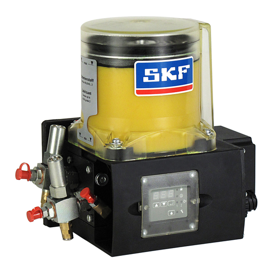
- Page 3 Page 1 Next Chapter Operating Instructions KFA, KFAS Pump Units of Series KFA and KFAS with Control Unit Keep for future use!
- Page 4 EC Machinery Directive 98/37/EEC Piston pump with reservoir type KFA10 Willy Vogel Aktiengesellschaft We hereby declare that the piston pumps with Motzener Straße 35/37, 12277 Berlin reservoir of type that it conforms to the essential safety requirements...
- Page 5 Piston pump with reservoir type KFA1, KFAS1 Willy Vogel Aktiengesellschaft • Motzener Straße 35/37, 12277 Berlin The safety hints contained in the documentation supplied along with the item shall be observed. that it conforms to the essential safety requirements...
- Page 6 Page 4 Next Chapter Operating Instructions KFA, KFAS Safety hints 6 Display mode 27 Contents Installation 8 Programming 29 Installation dimensions 9 Starting the programming mode 29 Pump unit versions 9 Changing the lubrication interval times 29 Pump elements 10 Changing the system monitoring 30 Replacing pump elements 11 Changing the operating mode 30...
- Page 7 Page 5 Contents Chapter Operating Instructions KFA, KFAS KFAS with control unit Installation Page 8 Pressure relief valve Page 12 Filling Page 12 Electrical connection Vehicles Control general Electrical connection Industrial Page 14 Page 22 applications Page 17 Pump elements Page 10...
- Page 8 The units may be pressurized. Therefore, they • The Vogel pump units type KFA and KFAS are caused by the installation of components or must be made pressure-less before any extension designed for the supply of centralized lubrication spare parts other than genuine Vogel work, modifications or repairs are carried out.
- Page 9 Page 7 Contents Chapter Operating Instructions KFA, KFAS Permitted lubricants Transport and storage Greases up to NLGI grade 2 DIN 51818 and a The pump units KFA and KFAS are packed in flow pressure of 700 mbars maximum. conformity with standard packaging practice such The release list of permitted lubricants is updated that the regulations in the country of destination on an ongoing basis and is available from the...
- Page 10 Page 8 Contents Chapter Operating Instructions KFA, KFAS 2. Installation General Mount the KFA and KFAS pump units to the vehicle When drilling, pay attention to the or machine with the 3 supplied M8 bolts, washers following possible hazards: The pump units of the KFA and KFAS series are and self-locking nuts.
- Page 11 Page 9 Contents Chapter Operating Instructions KFA, KFAS 2.1 Installation dimensions 2.2 Pump unit versions Weight with filled lubricant reservoir: Type Application Function Control KFAS1 3.7 kg, KFA10 4.8 kg KFA1 Vehicle 12 V or 24 V DC Without level monitoring KFA1-M Industry 24 V DC...
- Page 12 Page 10 Contents Chapter Operating Instructions KFA, KFAS 2.3 Pump elements The pump units KFA and KFAS are fitted with two All pump elements are provided with an internal lubricant outlet ports. To each outlet port, a separate thread M14x1.5 for connection to a pressure pump element for an independent progressive relief valve with tube port for steel tubes 6 mm feeder circuit can be connected.
- Page 13 Page 11 Contents Chapter Operating Instructions KFA, KFAS 2.4 Replacing pump elements Mount and dismount pump elements Step 2: Step 3: only when unit is disconnected from Remove bothersome lubricant between the fixing Pull piston of the new pump element as far as power supply.
- Page 14 Page 12 Contents Chapter Operating Instructions KFA, KFAS 2.5 Pressure relief valves 2.6 Lubricant filling The pressure relief valve is used to protect the The lubricant is filled in via the conical head entire lubrication system against excessive internal lubrication nipple DIN 71412-AM10x1 with a pressures.
- Page 15 Page 13 Contents Chapter Operating Instructions KFA, KFAS 2.7 Level monitoring 2.8 Bleeding the system • Initial filling Visual Disconnect the main lines from the unit. Operate the pump until the lubricant emerging from the Which lubricants may be used with the units may The transparent reservoir enables you to visually pressure relief valve is free of bubbles.
- Page 16 Page 14 Contents Chapter Operating Instructions KFA, KFAS 3. Electrical connection - vehicles Mind voltage values specified on 3.1 General electrical specifications nameplate! Rated voltage Typical power Starting current Back-up fuse input (load- (ca. 20 ms) dependent) KFA1... / KFAS1... 24 V DC 0.5 A ca.
- Page 17 Page 15 Contents Chapter Operating Instructions KFA, KFAS KFA1 without level monitoring KFA1-W with level monitoring KFA1, KFA1-W Cable set Cable set Mind voltage values given on nameplate Order Length of Length of Order Length of Length of and in section 3.1 ! number corrugated tube cores...
- Page 18 Page 16 Contents Chapter Operating Instructions KFA, KFAS KFAS1, KFAS1-W Cable sets Mind voltage values given on nameplate KFAS1/KFAS1-W Order Length of Length of and in section 3.1 ! without cycle switch monitoring number corrugated tube cores The unit is connected via the 7-pole circular PINS 5 and 6 have no function.
- Page 19 Page 17 Contents Chapter Operating Instructions KFA, KFAS 4. Electrical connection – industrial applications Mind voltage values specified on 4.1 General electrical specifications nameplate! Rated Typical power Pump starting Max. Observe the information and instructions voltage input (load- current back-up fuse contained in the operating manual and func- dependent) (ca.
- Page 20 Page 18 Contents Chapter Operating Instructions KFA, KFAS KFA1-M, KFA1-M-W Supply voltage 24 V DC KFA1-M without level monitoring KFA1-M-W with level monitoring This unit is provided only with pin-and-socket This unit is provided with the pin-and-socket Mind voltage values specified on connector X1.
- Page 21 Page 19 Contents Chapter Operating Instructions KFA, KFAS 4.3 KFAS1-M, KFAS1-M-W 4.4 KFAS1-M-Z, KFAS1-M-W-Z Supply voltage 24 V DC KFAS1-M These units are provided with the pin-and-socket connector X1 for the voltage supply and with a The KFAS1-M unit is provided only with the pin- Mind voltage values specified on circular pin-and-socket connector M12x1 for con- and-socket connector X1.
- Page 22 Page 20 Contents Chapter Operating Instructions KFA, KFAS 4.5 Color coding table External cycle switch 7-pole pin-and-socket connector X1 Only for units KFAS1-M-Z and KFAS1-M-W-Z ! X1- PIN Color code Core color KFAS1-M-Z KFAS1-M-Z KFAS1-M-W-Z KFAS1-M-W-Z brown RD-BK red-black blue pink black black...
- Page 23 Page 21 Contents Chapter Operating Instructions KFA, KFAS KFA10 without level monitoring KFA10-W with level monitoring 4.6 KFA10, KFA10-W Supply voltage This unit is provided only with pin-and-socket This unit is provided with the pin-and-socket con- 115 V or 230 V AC 3 A 50/60 Hz connector X1.
- Page 24 Page 22 Contents Chapter Operating Instructions KFA, KFAS 5. Display and control unit The display and control unit is protected by a LED display transparent plastic cover against splashing water and mechanical damage. For programming, the cover has to be dismounted and, following •...
- Page 25 Page 23 Next Chapter Operating Instructions KFA, KFAS 5.1 3-digit LED display Display Function Description • During normal operation, the display is off. It is t = TIMER The control unit operates as a time- Part of lubrication cycle activated by briefly operating one of the two PA = PAUSE controlled contact maker (TIMER) Entered and displayed value...
- Page 26 Page 24 Contents Chapter Operating Instructions KFA, KFAS Display Function Description • Monitoring OFF The monitoring function PS and CS is No system monitoring deactivated Cycle Switch Cycle switch monitoring is active • The cycle switch is monitored for signal transmission during the pump running time CONTACT.
- Page 27 Page 25 Contents Chapter Operating Instructions KFA, KFAS 5.2 Display via light-emitting LED lights = display mode LED flashes = programming mode diodes Operating voltage is applied to pump Value for PAUSE can be changed unit and control unit. The system is in PAUSE the PAUSE state h/lmp...
- Page 28 Page 26 Contents Chapter Operating Instructions KFA, KFAS 5.3 Operation via pushbuttons Pushbutton Operating possibilities • Operating the button during PAUSE will initiate an intermediate lubricating cycle • Fault messages are acknowledged and cleared • Automatically activate the display in the display mode •...
- Page 29 Page 27 Next Chapter Operating Instructions KFA, KFAS 6. Display mode Step Display Current operating state is indicated Lighting of the LED indicators signifies that the Example: Timer is in Pause mode unit is in the display mode. No flashing ! Using Press briefly this mode, the user can have current settings and operating parameters displayed.
- Page 30 Page 28 Contents Chapter Operating Instructions KFA, KFAS Step Display Monitoring deactivated or monitoring or monitoring via pressure (factory setting) via cycle switch switch. Is not permitted for progressive systems! Indicates operating hours 10 / 11 Example: Part 1 of total Part 2 of total value, Total value: 00533.8 h value.
- Page 31 Page 29 Contents Chapter Operating Instructions KFA, KFAS 7. Programming Step Display 000 in display flashes • (code 000 factory setting) Programming always starts with Press for more than 2s steps 1 and 2! • You can see from the flashing of the LED Automatically indicates first parameter indicators that the programming mode is Example: „Pause in timer operation“...
- Page 32 Page 30 Contents Chapter Operating Instructions KFA, KFAS 7.3 Changing the system monitoring 7.4 Changing the operating mode Carry out steps 1 and 2! Carry out steps 1 and 2! Step Display Step Display monitoring menu is Changes from Timer mode to Counter mode displayed (only possible with...
- Page 33 You will have Press appropriate to return the pump unit in this case to your key until dealer or local VOGEL office. LED indicators flash Important! Code 000 Do not use the figures 321 as new code.
- Page 34 Page 32 Contents Chapter Operating Instructions KFA, KFAS 8. Operating modes 8.1 Timer mode 8.3 No system monitoring 8.5 Level monitoring Pause and pump operation dependent on time In this mode of operation, the lubrication cycle is An installed level monitoring facility is controlled exclusively by the preset values for always active.
- Page 35 Page 33 Contents Chapter Operating Instructions KFA, KFAS 8.6 Monitoring via cycle switch This function can be used only in centralized lubrication systems with progressive feeders. For greases up to NLGI grade 2. The cycle switch is used to monitor the movements of the pistons in the progressive feeder during the CONTACT time and in the block operating mode.
- Page 36 Page 34 Contents Chapter Operating Instructions KFA, KFAS 9. Technical data Max. operating pressure 300 bars Applicable technical standards and directives -25 °C to +75 °C Permissible operating temperature 95 /54/ EC (Vehicles) 0 to +40 °C 89/336/EEC (Electromagnetic Compatibility) Number of outlets max.
- Page 37 Page 35 Contents Chapter Operating Instructions KFA, KFAS 10. Faults Check level in reservoir at regular 10.1 Displaying faults intervals. If the reservoir has been emptied completely, the entire system Start display mode with one of the two keys must be bled after topping up. Operate until fault is displayed.
- Page 38 Any works beyond the above-mentioned 0.1 hour = 6 minutes. The memory cannot be scope shall be performed only by erased. approved VOGEL service personnel. Fill in clean grease only. The service life of the pump elements and lubricated machine elements depends to a decisive extent on the cleanness of the lubricants used.
- Page 39 Page 37 Contents Next Chapter Operating Instructions KFA, KFAS 10.5 Block operation The control unit responds to a missing signal from A total of three lubrication cycles are the cycle switch by changing over to the block carried out with interrogation of the cycle mode.
- Page 40 Page 38 Next Chapter Operating Instructions KFA, KFAS 10.6 Pump faults Fault Cause Remedy • • Mechanical damage, e.g., motor Exchange pump Pump defective. Disconnect main lubricant line at outlet of pressure Motor does not run during activated pump relief valve running time Disconnect electrical connection Unscrew three fastening screws...
- Page 41 Page 39 Contents Chapter Operating Instructions KFA, KFAS Fault Cause Remedy • Pump element does not build up Exchange pump element pressure, pump element is worn. Pay attention to: Metering mark with grooves (Can be seen from the fact that the outlet can be kept closed with the finger when the main line is dismounted.)
- Page 42 Page 40 Contents Chapter Operating Instructions KFA, KFAS Service in Germany WILLY VOGEL AG WILLY VOGEL AG Technical Sales Office Technical Sales Office Sinstorfer Kirchweg 74-92 Duisburger Straße 44 21077 Hamburg 90451 Nürnberg (++49) 40-76 10 28 74 / 75...
- Page 43 P.O. Box 38955 Italy Belgium and Luxembourg STERLING HYDRAULICS LTD. Howick Sterling House, Crewkerne BERGER VOGEL s.r.l. WILLY VOGEL BELGIUM BVBA Auckland Somerset TA 18 8LL Via Mambretti, 9 Drevandaal 5 (++64) 9-576 96 28 (++44) 14 60-7 22 22...
- Page 44 Taiwan KARL HALWACHS FAHRZEUGTECHNINK Spain, Portugal, Marocco GES.M.B.H. & CO. KG Florastraße 5 CHANGHUA CHEN YING WILLY VOGEL IBERICA, S.A. Scheibelgarten 533 3005 Bern OIL MACHINE CO., LTD. Avd. de Suiza n° 3 2870 Aspang (++41) 31-3 52 64 26 9F., 1, Lane 83, Sec.
- Page 45 (++90) 212-2 21 12 27/28 /29 (++90) 212-2 21 74 88 E-mail: hidropak@superonline.com Hungary, Rumana, Bulgaria, Ex-Yugoslavia, Albania WILLY VOGEL HUNGARIA Kft. Felvèg u. 4. 2051 Biatorbàgy (++36) 23-312-431 Current list of all service partners or in (++36) 23-310 441 the Internet at: www.vogelag.com...
- Page 46 Start Chapter Willy Vogel Aktiengesellschaft Motzener Straße 35 / 37 Gottlieb-Daimler-Straße 7 12277 Berlin 63128 Dietzenbach 97 04 44, 12704 Berlin 2058, 63120 Dietzenbach (++49) 30-7 20 02-227 (++49) 60 74-40 96-0 (++49) 30-7 20 02-111 (++49) 60 74-40 96-33 info@vogel-berlin.de...
- Page 47 Continuer Chapitre KFA, KFAS Groupes de pompe Instructions de service...
Need help?
Do you have a question about the KFA Series and is the answer not in the manual?
Questions and answers