
Related Manuals for Sennheiser EW 100 G4 Series


Summary of Contents for Sennheiser EW 100 G4 Series
- Page 1 G4 100 series Instruction Manual Sennheiser electronic GmbH & Co. KG Am Labor 1, 30900 Wedemark, Germany, www.sennheiser.com ew 100 G4 - v .
-
Page 2: Table Of Contents
Color labeling set 18 Microphone clamp 18 The frequency bank system 19 Installing and starting up ew 100 G4 series devices Installing the EM 100 G4 21 Connectors on the rear of the device 22 Product overview for the rear side of the... - Page 3 Mounting a single antenna splitter in a rack 53 Mounting two antenna splitters side by side in a rack Using ew 100 G4 series devices 56 Using the EM 100 G4 58 Operating elements on the front of the device 59...
- Page 4 Frequency Preset menu item 76 Name menu item 77 AF Out menu item 78 Equalizer menu item 79 Auto Lock menu item 80 Advanced menu item 81 Advanced -> Tune menu item 82 Only adjusting the frequency 82 Setting the channel and frequency 82 Advanced ->...
- Page 5 Deactivating the RF signal (RF mute) 106 Deactivating the RF signal with the switch 106 MUTE Deactivating the RF signal with the button 108 ON/OFF Lock-off function 109 Displays on the SK 100 G4 bodypack transmitter display panel 110 Select a standard display 111 Buttons for navigating the SK 100 G4 menu 112 Navigating through the menu 112 Making changes in a menu item 112...
- Page 6 AF characteristics 134 Overall device 135 SK 100 G4 136 RF characteristics 136 AF characteristics 136 Overall device 137 ASA 214 138 Specifications 138 Block diagram 139 Pin assignment 140 3.5 mm stereo jack plug 140 3.5 mm mic jack plug 140 3.5 mm line jack plug 140 6.3 mm stereo jack plug, balanced (audio in/loop out) 6.3 mm mono jack plug, unbalanced 141...
-
Page 7: Overview
You can find information about the individual products in the ew 100 G4 se- ries under “ew 100 G4 series products”. For information about the available accessories, see “Accessories”. You can find information about the ew 100 G4 series frequency bank sys- tem under “The frequency bank system”. -
Page 8: Ew 100 G4 Series Products
You can find technical specifications about the individual products un- der “Specifications”. • You can find information about installing the products under “Installing and starting up ew 100 G4 series devices”. • You can find information about operating the products under “Using ew 100 G4 series devices”. -
Page 9: Em 100 G4 Rack Receiver
EM 100 G4 rack receiver ► You can find more detailed information about the EM 100 G4 in the following sections: • Installation and Startup: “Installing the EM 100 G4” • Operation: “Using the EM 100 G4” • Technical Data: “EM 100 G4”... -
Page 10: Skm 100 G4 Handheld Transmitter
SKM 100 G4 handheld transmitter ► SKM 100 G4 variant: ► SKM 100 G4-S variant: ► The SKM 100 G4 handheld transmitter is also available in the SKM 100 G4- S variant with an integrated mute switch. You can find more detailed information about the SKM 100 G4 in the following sections: •... -
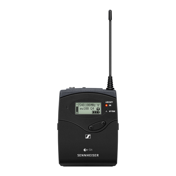
Page 11: Sk 100 G4 Bodypack Transmitter
SK 100 G4 bodypack transmitter ► You can find more detailed information about the SK 100 G4 in the following sections: • Installation and Startup: “Installing the SK 100 G4” • Operation: “Using the SK 100 G4” • Technical Data: “SK 100 G4”... -
Page 12: Accessories
Accessories Accessories A variety of accessories are available for the ew 100 G4 series. -
Page 13: Microphones And Cables
Dynamic, omni-directional, black 506772 You can find more information about the individual microphone mod- ules on their respective product pages at www.sennheiser.com. Headset and Lavalier microphones We recommend using the following Lavalier microphones and headset mi- crophones with the SK 100 G4 bodypack transmitter. -
Page 14: Line/Instrument Cables
506904 rectional, silver You can find more information about the individual microphones on their respective product pages at www.sennheiser.com. Line/instrument cables The following cables are available to connect instruments and line sources to the SK 100 G4 bodypack transmitter: •... -
Page 15: Rechargeable Battery And Charger
Accessories Rechargeable battery and charger BA 2015 rechargeable battery The BA 2015 rechargeable battery is designed for use with evolution wire- less G4 series handheld transmitters, bodypack transmitters and bodypack receivers. Article no. 009950 ► L 2015 charger The BA 2015 rechargeable battery can be charged in the L 2015 charger on its own or inside of the bodypack transmitter/bodypack receiver. -
Page 16: La 2 Charging Adapter
Accessories LA 2 charging adapter Charging adapter for L 2015 charger for charging SKM G4 handheld trans- mitters with installed BA 2015 rechargeable battery. Article no. 503162 ►... -
Page 17: Accessories For Rack Mounting
Accessories Accessories for rack mounting GA 3 rack mount kit 19” rack adapter for mounting the EM 100 G4, EM 300-500 G4 or SR IEM G4 in a 19” rack. Article no. 503167 ► AM 2 antenna front mounting kit Antenna front mounting kit for installing antenna connections on the front of the rack when using the EM 100 G4, EM 300-500 G4 or SR IEM G4 to- gether with the GA 3 rack mounting kit. -
Page 18: Antennas And Accessories
Accessories Antennas and accessories The following antenna components are available as accessory parts. Omni-directional antennas • A 1031-U, passive omni-directional antenna, article no. 004645 Directional antennas • A 2003 UHF, passive directional antenna, article no. 003658 • AD 1800, passive directional antenna, 1.8 GHz range, article no. 504916 Antenna splitter ►... -
Page 19: Additional Accessories
Accessories Additional accessories Color labeling set • KEN 2, color labeling set for SKM handheld transmitters, article no. 530195 ► Microphone clamp • MZQ 1, microphone clamp for SKM handheld transmitters, article no. 076670 ►... -
Page 20: The Frequency Bank System
The frequency bank system The frequency bank system There are different frequency ranges in the UHF band available for trans- mission. The following frequency ranges are available for the ew 100 G4 series: • A1 range: 470 – 516 MHz •... -
Page 21: Installing And Starting Up Ew 100 G4 Series Devices
INSTALLATION Installing and starting up ew 100 G4 se- ries devices You can find information about installing and connecting ew 100 G4 series devices in the following sections. • EM 100 G4 rack receiver >> “Installing the EM 100 G4”... -
Page 22: Installing The Em 100 G4
Installing the EM 100 G4 Installing the EM 100 G4 These sections contain detailed information about installing and starting up the EM 100 G4. You can find information about operating the EM 100 G4 under “Using the EM 100 G4”. -
Page 23: Connectors On The Rear Of The Device
Installing the EM 100 G4 Connectors on the rear of the device Product overview for the rear side of the EM 100 G4 ► Strain relief for the cable of the power supply unit • See “Connecting/disconnecting the EM 100 G4 to/from the power supply system”... -
Page 24: Connecting/Disconnecting The Em 100 G4 To/From The Power Supply System
Installing the EM 100 G4 Connecting/disconnecting the EM 100 G4 to/from the power supply system Only use the supplied power supply unit. It is designed for your receiver and ensures safe operation. To connect the EM 100 G4 to the power supply system: Insert the plug of the power supply unit into the DC IN socket of the re- ▷... -
Page 25: Creating A Data Network
Installing the EM 100 G4 Creating a data network You can cascade multiple EM 100 G4s to a multi-channel system using the two DATA RJ-10 interfaces (up to 12 receivers). You can perform a frequen- cy setup for the entire multi-channel system via this data network using the Easy Setup function. -
Page 26: Setting Up A Multi-Channel System With More Than
Installing the EM 100 G4 Setting up a multi-channel system with more than 12 receivers You can use the Easy Setup function to automatically set up a maximum of 12 receivers. If you assign the frequencies manually, however, you can use up to 20 re- ceivers in a multi-channel system (not possible in the TH, JB, K+ and 1G8 frequency ranges). -
Page 27: Outputting Audio Signals
Installing the EM 100 G4 Outputting audio signals The EM 100 G4 has a balanced XLR-3M output socket and an unbalanced 6.3 mm jack output socket. Always use only one of the two AF OUT output sockets for each chan- ▷... -
Page 28: Connecting Antennas
Installing the EM 100 G4 Connecting antennas To connect the supplied rod antennas: ▷ Connect the first rod antenna to the ANT I socket on the rear side of the EM 100 G4. Connect the second rod antenna to the ANT II socket on the rear side ▷... -
Page 29: Installing The Em 100 G4 In A Rack
Installing the EM 100 G4 Installing the EM 100 G4 in a rack CAUTION Rack mounting poses risks When installing the device in a closed or multi-rack assembly, please con- sider that, during operation, the ambient temperature, the mechanical loading and the electrical potentials will be different from those of devices which are not mounted into a rack. -
Page 30: Mounting A Single Receiver In A Rack
Installing the EM 100 G4 Mounting a single receiver in a rack To mount the receiver in a rack, you will need the GA 3 rack mounting kit (optional accessory). To fasten the mounting angle of the GA 3 rack mounting kit: Unscrew and remove the two recessed head screws (M4x8) on each ▷... -
Page 31: Mounting Two Receivers Side By Side In A Rack
Installing the EM 100 G4 Mounting two receivers side by side in a rack When you mount two receivers side by side, it is only possible to front mount antennas when you use the ASA 214 antenna splitter in com- bination with the AM 2 front mounting kit and an additional GA 3 rack mounting kit, To mount the receiver using the GA 3 rack mounting kit (optional accesso-... -
Page 32: Installing The Skm 100 G4
Installing the SKM 100 G4 Installing the SKM 100 G4 These sections contain detailed information about installing and starting up the SKM 100 G4. You can find information about operating the SKM 100 G4 under “Using the SKM 100 G4”. -
Page 33: Inserting And Removing The Batteries/Rechargeable Batteries
Inserting and removing the batteries/rechargeable batteries You can operate the wireless microphone either with batteries (AA, 1.5 V) or with the rechargeable Sennheiser BA 2015 battery. Screw the rear part of the wireless microphone in the direction of the ▷... -
Page 34: Battery Status
Installing the SKM 100 G4 Battery status Charge status of the batteries: ► Charge status is critical (LOW BATT): ►... -
Page 35: Replacing The Microphone Module
Installing the SKM 100 G4 Replacing the microphone module You can find a list of the recommended microphone modules for the hand- held transmitter under “Microphones and cables”. To change the microphone module: Unscrew the microphone module. ▷ ▷ Screw the desired microphone module on. ►... -
Page 36: Changing The Colored Ring
Installing the SKM 100 G4 Changing the colored ring To change the colored ring: ▷ Pull the colored ring off as shown in the diagram. ► Attached a colored ring in the color you want as shown in the diagram. ▷... -
Page 37: Installing The Sk 100 G4
Installing the SK 100 G4 Installing the SK 100 G4 These sections contain detailed information about installing and starting up the SK 100 G4. You can find information about operating the SK 100 G4 under “Using the SK 100 G4”. -
Page 38: Inserting And Removing The Batteries/Rechargeable Bat
Installing the SK 100 G4 Inserting and removing the batteries/rechargeable batteries You can operate the bodypack transmitter either with batteries (AA, 1.5 V) or with the rechargeable Sennheiser BA 2015 battery. Press the two catches and open the battery compartment cover. ▷ ▷... -
Page 39: Battery Status
Installing the SK 100 G4 Battery status Charge status of the batteries: ► Charge status is critical (LOW BATT): ►... -
Page 40: Connecting A Microphone To The Sk 100 G4
Installing the SK 100 G4 Connecting a microphone to the SK 100 G4 You can find a list of recommended Lavalier and headset microphones for the bodypack transmitter under “Microphones and cables”. To connect a microphone to the bodypack transmitter: Insert the cable’s 3.5 mm jack plug into the MIC/LINE socket on the ▷... -
Page 41: Connecting An Instrument Or Line Source To The Sk 100 G4
To do this, you will need the Ci 1-N (6.3 mm jack plug on a lockable 3.5 mm jack plug) or CL 2 (XLR-3F plug on lockable 3.5 mm jack plug) Sennheiser cables. To connect an instrument or line source to bodypack transmitter: ▷... -
Page 42: Attaching The Bodypack Transmitter To Clothing
Installing the SK 100 G4 Attaching the bodypack transmitter to clothing You can use the belt clip to attach the bodypack transmitter to your waist- band or on a guitar strap. The belt clip is detachable so that you can also attach the bodypack trans- mitter with the antenna pointing downwards. -
Page 43: Installing The Asa 214
Installing the ASA 214 Installing the ASA 214 These sections contain detailed information about installing and starting up the ASA 214. You can find information about operating the ASA 214 under “Using the ASA 214”. -
Page 44: Connectors On The Rear Of The Device
Installing the ASA 214 Connectors on the rear of the device Product overview for the rear side of the ASA 214 ► ANT RF IN B BNC socket • Antenna input of diversity branch B • See “Connecting antennas” RF OUT A BNC socket •... -
Page 45: Connecting/Disconnecting The Asa 214 To/From The Power Supply System
Installing the ASA 214 Connecting/disconnecting the ASA 214 to/from the power supply system To supply power to the ASA 214, the connected receivers and any antenna amplifiers used, you will need the NT 1-1 power supply unit. Only use the supplied NT 1-1 power supply unit. It is designed for your an- tenna splitter and ensures safe operation. -
Page 46: Connecting Receivers To The Asa 214
Connecting receivers to the ASA 214 You can connect and operate up to four stationary receivers to the ASA 214. Sennheiser receivers of the ew G4 and ew G3 series can also be supplied with power from the ASA 214. The following receivers are compatible: evolution wireless G4: •... - Page 47 Installing the ASA 214 To connect the receivers to the ASA 214 antenna splitter: Connect one of the receiver’s antenna inputs to one of the BNC sockets ▷ A1 to A4 using one of the supplied BNC cables. The compatible receivers listed above do not require their own power supply.
-
Page 48: Connecting Antennas
Installing the ASA 214 Connecting antennas For more information about antennas and antenna accessories, see “Antennas and accessories”. In order to ensure optimal reception even in the case of poor recep- tion conditions, we recommend using remote antennas. Connecting remote antennas ▷... -
Page 49: Information On Antenna Amplifiers And Cable Lengths
Installing the ASA 214 Information on antenna amplifiers and cable lengths The following table shows which cable lengths require the use of the AB 3 or AB 4 antenna amplifier as well as the maximum recommended cable lengths. Device Frequen- Number Max. - Page 50 Installing the ASA 214 • Aw+ range: 470 – 558 MHz • Gw range: 558 – 626 MHz • GBw range: 606 – 678 MHz • Bw range: 526 – 698 MHz • Cw range: 718 – 790 MHz • Dw range: 790 –...
- Page 51 Installing the ASA 214 Configuring multi-channel systems The following options for connecting multi-channel systems are possible: Option 1: Two antennas supply a 4-channel system...
-
Page 52: Reset
Using the SKM 100 G4 Advanced > Reset menu item • Resetting the wireless microphone ► When you reset the wireless microphone, only the selected settings of the pilot tone and the U frequency bank are retained. Advanced > Software Revision menu item •... - Page 53 Using the SK 100 G4 Using the SK 100 G4 These sections contain detailed information about using the SK 100 G4. You can find information on installation and startup of the SK 100 G4 under “Installing the SK 100 G4”.
- Page 54 Using the SK 100 G4 Operating elements of the SK 100 G4 bodypack transmitter ► Display panel • See “Displays on the SK 100 G4 bodypack transmitter display panel” Operation and battery indicator, red LED • illuminated = ON See “Switching the SK 100 G4 bodypack transmitter on and off” •...
- Page 55 ▷ Press the two catches and open the battery compartment cover. To switch on the SK 100 G4: Hold down the ON/OFF button until the Sennheiser logo appears on the ▷ display. To switch off the SK 100 G4: Hold down the ON/OFF button until the display goes off.
- Page 56 Using the SK 100 G4 Muting the bodypack transmitter (AF mute) You can deactivate the audio signal with the MUTE switch. To do this, the MUTE switch function must be configured to AF On/Off. You can find more information about this subject under “Advanced > Mute Mode menu item”.
- Page 57 Using the SK 100 G4 Deactivating the RF signal (RF mute) You can deactivate the RF signal in two ways: Deactivating the RF signal with the MUTE switch You can deactivate the RF signal with the MUTE switch. To do this, the MUTE switch function must be configured to RF On/Off. You can find more information about this subject under “Advanced >...
- Page 58 Using the SK 100 G4 ▷ Slide the MUTE switch to the MUTE position. The RF signal is deactivated. The message MUTE is shown in the dis- play and the transmission icon no longer appears.
- Page 59 Using the SK 100 G4 Deactivating the RF signal with the ON/OFF button You can deactivate the RF signal with the ON/OFF button. To deactivate the RF signal: ▷ Short-press the ON/OFF button. RF Mute On? appears. ▷ Press the SET button. The RF signal is deactivated.
- Page 60 Using the SK 100 G4 Lock-off function You can set the automatic lock-off function in the Auto lock menu (see “Buttons for navigating the SK 100 G4 menu”). When you have switched on the lock-off function, you will have to turn the transmitter off and on again in order to operate it.
- Page 61 Using the SK 100 G4 Displays on the SK 100 G4 bodypack transmitter display panel You can view the following information on the transmitter display. ► AF audio level • Displays the audio level with peak hold function • See “Sensitivity menu item” Frequency •...
- Page 62 Using the SK 100 G4 >> “Buttons for navigating the SK 100 G4 menu” >> “Setting options in the menu” Select a standard display Press the UP or DOWN buttons to select a standard display. ▷ Frequency/Name standard display ► 548.100 ew100 G4 MUTE...
- Page 63 Using the SK 100 G4 Buttons for navigating the SK 100 G4 menu Navigating through the menu To open the menu: Press the SET button. ▷ The operating menu is shown on the transmitter display panel. To open a menu item: ▷...
- Page 64 Using the SK 100 G4 Setting options in the menu In the SK 100 G4 menu, you can configure the following settings. Adjusting the input sensitivity ▷ See “Sensitivity menu item” Setting the frequency bank and the channel ▷ See “Frequency Preset menu item” Entering a freely selectable name ▷...
-
Page 65: Frequency Preset Menu Item
Using the SK 100 G4 Sensitivity menu item • Adjusting the input sensitivity – AF audio level ► Setting range: 0 dB to –60 dB in 6 dB steps. The AF audio level is also displayed when the bodypack transmitter is mut- ed, e.g. -
Page 66: Name Menu Item
Using the SK 100 G4 Name menu item • Entering names ► In the Name menu item you can enter any name you want for the bodypack transmitters (e.g. the names of the musicians). The name can be shown in the Frequency/Name Name/Channel stan-... -
Page 67: Advanced Menu Item
Using the SK 100 G4 Advanced menu item In the Advanced submenu you can configure enhanced settings. The following sub-items are available: Adjusting the transmission frequencies for the U frequency bank See “Advanced > Tune menu item” ▷ Configuring the MUTE switch See “Advanced >... -
Page 68: Advanced > Tune Menu Item
Using the SK 100 G4 Advanced > Tune menu item • Configuring the transmission frequency and frequency bank U When you have configured the bodypack transmitter to a system bank and you call up the Tune menu item, channel 1 of the frequency bank U is auto- matically set. - Page 69 Using the SK 100 G4 Advanced > Mute Mode menu item • Configuring the MUTE switch ► AF On/Off mode • If set to position MUTE, the audio signal is muted. RF On/Off mode • If set to position MUTE, the RF signal is deactivated. Disabled mode •...
-
Page 70: Advanced > Pilot Tone Menu Item
Using the SK 100 G4 Advanced > Pilot Tone menu item • Activating/deactivating pilot tone transmission ► The pilot tone has an inaudible frequency that is sent from the transmitter and evaluated by the receiver. It supports the receiver’s squelch function. Advanced >... - Page 71 Establishing a radio link Establishing a radio link To establish a radio link between the transmitter and receiver, the same frequency must be set in both devices. You can do this in a number of different ways: 1. Use the Easy Setup function to perform an automatic frequency set- up (see “Easy Setup menu item”).
- Page 72 Synchronizing devices Synchronizing devices You can synchronize ew 100 G4 series transmitters and receivers via the receiver’s infrared interface. The following Parameters are transferred to the transmitters: • Frequency Preset >> currently configured frequency (see “Frequency Preset menu item”) •...
- Page 73 Synchronizing devices of the SKM 100 G4 handheld transmitter” and “Operating elements of the SK 100 G4 bodypack transmitter”) in front of the infra-red interface of the receiver (see “Operating elements on the front of the device”). The parameters are transferred to the transmitter. The blue LED blinks during transmission.
- Page 74 Using the ASA 214 Using the ASA 214 These sections contain detailed information about operating the ASA 214. You can find information on installation and startup of the ASA 214 under “Installing the ASA 214”.
- Page 75 Using the ASA 214 Operating elements on the front of the device ► STANDBY button • See “Switching the ASA 214 on and off” LED: Operation indicator...
- Page 76 Using the ASA 214 Switching the ASA 214 on and off To switch on the antenna splitter: ▷ Short-press the STANDBY button. The antenna splitter switches on and the power LED turns green. The RF signals of the connected antennas are distributed to all con- nected receivers.
- Page 77 SPECIFICATIONS Overview In the sections below, you can find information about the different variants of the products in the ew 100 G4 series as well as technical data for the in- dividual products. • Product variants and frequency variants >> “Product variants”...
- Page 78 Product variants Product variants EM 100 G4 product variants Made in Germany ► EM 100 G4-A1 470 – 516 MHz Art. no. 507603 EM 100 G4-A 516 – 558 MHz Art. no. 507604 EM 100 G4-GB 606 – 648 MHz Art.
- Page 79 Product variants SKM 100 G4 product variants Made in Germany SKM 100 G4-S ► SKM 100 G4-S-A1 470 – 516 MHz Art. no. 507594 SKM 100 G4-S-A 516 – 558 MHz Art. no. 507595 SKM 100 G4-S-GB 606 – 648 MHz Art.
- Page 80 Product variants SKM 100 G4-S ► SKM 100 G4-A1 470 – 516 MHz Art. no. 508001 SKM 100 G4-A 516 – 558 MHz Art. no. 508002 SKM 100 G4-AS 520 – 558 MHz Art. no. 508003 SKM 100 G4-G 566 – 608 MHz Art.
- Page 81 Frequency tables Frequency tables You can find frequency tables for all available frequency ranges in the download section of the Sennheiser website uneer www.sennheiser.com/ download. Download area of the Sennheiser website Enter ew G4 into the search bar to show the frequency tables.
- Page 82 Specifications Specifications You can find product-specific technical data in the sections below.
-
Page 83: Off
EM 100 G4 RF characteristics ► Modulation Wideband FM Receiving frequency ranges A1: 470 – 516 MHz A: 516 – 558 MHz AS: 520 – 558 MHz G: 566 – 608 MHz GB: 606 – 648 MHz B: 626 – 668 MHz C: 734 –... - Page 84 AF characteristics ► Compander system Sennheiser HDX EQ presets (switchable, act on line and monitor outputs): Preset 1: Flat Preset 2: Low Cut –3 dB at 180 Hz Preset 3: Low Cut High Boost –3 dB at 180 Hz +6 dB at 10 kHz...
-
Page 85: Skm 100 G4
RF output power at 50 ? Max. 30 mW Pilot tone squelch Can be switched off AF characteristics ► Compander system Sennheiser HDX AF frequency response 80 – 18,000 Hz Signal-to-noise ratio ≥ 110 dBA (1 mV, peak deviation) Total harmonic distortion (THD) ≤... - Page 86 Overall device ► Temperature range -10 °C to +55 °C (14 °F to 131 °F) Power supply 2 AA batteries, 1,5 V or BA 2015 accupack Nominal voltage 3 V battery / 2.4 V rechargeable battery Power consumption at nominal voltage typically 180 mA with transmitter switched off ≤...
- Page 87 RF output power at 50 ? Max. 30 mW Pilot tone squelch Can be switched off AF characteristics ► Compander system Sennheiser HDX AF frequency response Microphone: 80 – 18,000 Hz Line: 25 – 18,000 Hz Signal-to-noise ratio ≥ 110 dBA (1 mV, peak deviation) Total harmonic distortion (THD) ≤...
- Page 88 Overall device ► Temperature range -10 °C to +55 °C (14 °F to 131 °F) Power supply 2 AA batteries, 1,5 V or BA 2015 accupack Nominal voltage 3 V battery 2.4 V rechargeable battery Power consumption at nominal voltage typically 180 mA with transmitter switched off ≤...
- Page 89 ASA 214 Specifications ► ASA 214 antenna splitter 2 × 1:4 or 1 × 1:8, active Connection cable 8 pieces, 50 cm, BNC Frequency range ASA 214-UHF: 470 – 870 MHz at –3 dB ASA 214-1G8: 1785 – 1805 MHz at –3 dB Amplification In A –...
- Page 90 Block diagram...
- Page 91 Pin assignment Pin assignment 3.5 mm stereo jack plug ► • Plug for headphone and earphone cables, e.g. IE 4. • Connect to: • EK IEM G4 • EK 500 G4 3.5 mm mic jack plug ► • Plug for lavalier and headset microphone, e.g. ME 2. •...
- Page 92 Pin assignment 6.3 mm mono jack plug, unbalanced ► • Connect to: • EM 100 G4 Audio Out • EM 300-500 G4 Audio Out 6.3 mm stereo jack plug for headphone jack ► • Connect to: • EM 100 G4 headphone input •...
- Page 93 Cleaning and maintenance Cleaning and maintenance Note the following information when cleaning and maintaining evolution wireless G4 series products. CAUTION Liquids can damage the products’ electronics. Liquids entering the product housing can cause a short-circuit and damage the electronics. ▷ Keep all liquids away from the products.
- Page 94 Cleaning and maintenance ▷ Screw the sound inlet basket back onto the microphone module. From time to time, you should also clean the microphone module contacts: ▷ Wipe the contacts of the microphone module with a soft, dry cloth.
Need help?
Do you have a question about the EW 100 G4 Series and is the answer not in the manual?
Questions and answers