
Related Manuals for SureShot AC110


Summary of Contents for SureShot AC110
- Page 1 INTELLISHOT & FLEXOSHOT REFRIGERATED DAIRY DISPENSER MODELS AC110, AC220, AC230, AC320, & AC330 OPERATIONS MANUAL OPERATIONS MANUAL D-19-032 Rev. P...
-
Page 3: Table Of Contents
TABLE OF CONTENTS User Options (or Options) ............. 20 TABLE OF CONTENTS ............III Drink Counts ................20 LIST OF FIGURES ..............IV Refrigeration ................20 LIST OF TABLES ..............V Service ..................20 USER OPTIONS ................21 LEGEND ................. V Display Temperature Units............ -
Page 4: List Of Figures
LIST OF FIGURES Figure 1: Main exterior components of the AC110-PC ......................1 Figure 2: Main interior components of the AC320-FP ......................1 Figure 3: Main exterior components AC230-SS with self-serve dispense handles and illuminated display .... 2 Figure 4: Main exterior components AC330-SS with low touch cup levers and illuminated display ......2 Figure 5: Illuminated door display ............................ - Page 5 LIST OF TABLES Table 1: Specifications ................................3 Table 2: Power requirements ..............................3 Table 3: Refrigerant ..................................3 Table 4: Program mode buttons ............................. 17 Table 5: Side console display options ........................... 25 Table 6: Recommended cleaning schedule ......................... 27 LEGEND Note icon Explanations and reminders.
-
Page 6: Introduction
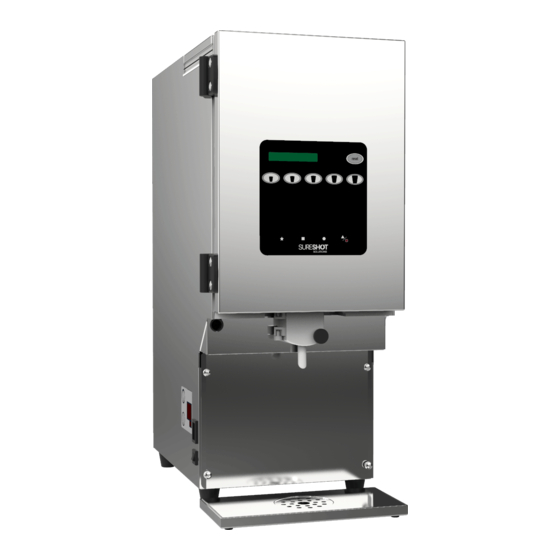
② ⑧ 9. Front panel 10. Catch tray ③ ⑨ ④ ⑩ Figure 1: Main exterior components of the AC110-PC Actual dairy dispenser may not be exactly as shown. ③ ④ ① 1. Door gasket 2. Job aid ② ⑤... -
Page 7: Main Components Of Flexoshot (Non-Portion-Control)
MAIN COMPONENTS OF FLEXOSHOT (NON-PORTION-CONTROL) ⑤ 1. Valve door 2. Side console (temp display/adjustment) 3. Power switch 4. Circuit breaker ① ⑥ 5. Illuminated door graphic 6. Product ID magnets ⑦ 7. Thumbscrew on valve door ② ⑧ 8. Self-serve dispense handles 9. -
Page 8: Specifications
SPECIFICATIONS Model: AC10 AC20 AC30 Weight (empty): 60 lbs / 27 kg 75 lbs / 34 kg 80 lbs / 36 kg Dimensions* 18" x 9.5" x 24" 22" x 12" x 24" 23.75" x 15.5" x 24" (LxWxH): 46 x 24 x 61 cm 56 x 31 x 61 cm 61 x 40 x 61 cm *Height is based on dispensers with 1-inch (2.5 cm) legs. -
Page 9: Receiving The Dispenser
RECEIVING THE DISPENSER INSPECT FOR DAMAGE Do not accept shipment if damage is extensive. Always note damage in detail with the carrier whether shipment is accepted or refused as proof for damage claims. If damage is found after accepting shipment: 1. -
Page 10: Setting Up The Dispenser
SETTING UP THE DISPENSER The dispenser must be placed on a horizontal surface. The surface must be strong enough to support the dispenser and a full product load. The dispenser must be level for the refrigeration system to work efficiently and for optimum dispense accuracy. Some models include adjustable legs to help level the dispenser if necessary. -
Page 11: Power Requirements
POWER REQUIREMENTS SureShot dairy dispensers require a power source receptacle with specifications as indicated on the product identification label. For more information, please refer to the Introduction in this manual. The power cord has a 3-prong attachment plug. This plug is designed to fit a receptacle with provisions for a grounding stud. -
Page 12: Turning On The Dispenser
2. Use a Phillips screwdriver to remove the screws on the right-hand side of the dispenser door (i.e., latch side). 3. Open the door display panel to reveal the door graphic. Door graphic Figure 6: Open door display panel 4. Remove the door graphic from the door display panel by sliding the left and right sides out from behind the frame. -
Page 13: Operating The Dispenser
SureShot dispensers are designed to accommodate three types of product packaging. Product may be packaged in a single-use 5 L/1 G or 10 L/2.5 G prefilled bag (contained in a SureShot product case), a bag-in-box (used with a SureShot ramp) or cartons (poured into a SureShot refillable tank). The model of dispenser is typically chosen according to the product packaging. -
Page 14: Figure 9: Dairy Bag Fitment Secured On Product Case Floor
3. Locate the top ring on the bag fitment (i.e., the ring closest to the bag). Slide the top ring of the fitment into the product case opening so that it is resting on the product case floor. Do not use the lower ring. Product Bag fitment case floor... -
Page 15: Bag-In-Box
Removing a Product Case and Empty Dairy Bag 1. Open the dispenser door. 2. Place a clean container under the tube to catch any residual product that may drain once the valve door is open. 3. Open the valve door by turning the black thumbscrew counterclockwise. 4. -
Page 16: Refillable Tank
6. Fold up the tube and pinch it just below the valve. This will push product out of the tube and up into the bag. 7. While holding the tube, close the valve door and turn the thumbscrew clockwise until the valve door is secure and the plunger activates, making a sound. -
Page 17: Figure 18: Flip Lid On Top Of Dispenser
1. Install a SureShot 3-inch (7.6 cm), pre-cut, white tube onto the spout of a clean, sanitized product tank by pushing the end of the tube fully onto the spout. -
Page 18: Figure 21: Fill-In-Place Model (Ac330-Fp)
FLEXOSHOT Non-Portion-Control, Fill-in-Place (with Dispenser Flip Lid) 1. Install a SureShot 3-inch (7.6 cm), pre-cut, white tube onto the spout of a clean, sanitized tank. If using a SureShot 10-inch (25.4 cm) tube, use sanitized, sharp scissors to cut the tube in half before installing it onto the tank. -
Page 19: Figure 23: Correct Tube Placement
Figure 24: Cutting the tube FLEXOSHOT Non-Portion-Control, Non-Fill-in-Place (without Dispenser Flip Lid) 1. Using sanitized, sharp scissors, cut a SureShot 10-inch (25.4 cm) crimped tube in half before installing it onto the product tank. There should be no jagged edges. Save the other half of the tube for another tank. -
Page 20: Dispensing Product
8. Place the tank in the product compartment above the correct valve with the tube facing out. 9. Centre the tube in the valve opening. Remove and discard the plastic covering if present. The tube should not be twisted, kinked, or pinched. Dispense tube Figure 26: Correct tube placement 10. -
Page 21: Portion-Control Dispensers
Dispensers with Cup Levers: 1. Using the lower half of a cup, push cup against the bottom of the cup lever. 2. Once the desired amount of product is dispensed, pull cup away from lever. For sanitation purposes, do not touch the cup lever with the lip of the cup or hands. Portion-Control Dispensers The button panel on a portion-control model is used to prepare beverages, dispense product, and access the dispenser’s software features. -
Page 22: Preparing A Beverage And Dispensing Product
A separate software features instruction sheet may be included with the dispenser for additional software customization options. Alternatively, contact SureShot Technical Assistance for guidance. In normal operating mode, the button panel display may toggle between Select Product or Select Size and the current product level (e.g., 10.0 L... -
Page 23: Program Mode Menu
PROGRAM MODE MENU Recipe/Target Adjust (Dispense Amounts) The recipe or preset dispense amounts are displayed in either imperial (fluid ounces/gallons) or metric (milliliters/liters) units of measurement. To manually adjust the recipe or dispense amounts: Press and hold the program mode button () until Recipe or Target Adjust is visible in the display. -
Page 24: Buttons
The light on the first and second button from the left, top row will illuminate. a. One product dispenser – The calibration percentages will be visible in the display (e.g., Milk 5% 0%). Place an empty cup under the dispense point. b. -
Page 25: Bag Selection (Or Bag Type) And Tank Selection
Temperature Display and Adjustment section in this manual. Service Service features are typically used by a service technician. In some circumstances, a technician from the SureShot Technical Assistance Centre may walk a user through a Service feature. IntelliShot & FlexoShot: Operations Manual Page 20... -
Page 26: User Options
Hidden buttons Figure 29: Button panel for the AC110 Display Temperature Units The Temp Units feature will add the current temperature of the product compartment in the display during normal operating mode. -
Page 27: Level Display
4. Press and hold the second button from the left, top row to change the display to liters or gallons. 5. Press and hold the program mode button () to save and return to normal operating mode. Level Display The Level Display feature will add the current level of each product in the display during normal operating mode. -
Page 28: Recipe By Region
2. Press the program mode button () repeatedly until Options or User Options is visible in the display. 3. Press the first button from the left, second row. Level Warning will be visible in the display. 4. Press and hold the first button from the left, second row to turn Level Warning on or off. 5. -
Page 29: Language
Language The software may be programmed with more than one language option (e.g., English, French, or Spanish). If available, follow the instructions to change the language. 1. Press and hold the program mode button () until Recipe or Target Adjust is visible in the display. -
Page 30: Adjusting Temperature With The Side Console
ADJUSTING TEMPERATURE WITH THE SIDE CONSOLE The two thermometer buttons on the left adjust the compartment’s temperature up or down. Cool temperature adjustment button (decreases the temperature) Temperature display Warm temperature adjustment button (increases the temperature and changes the display mode between d1 and d2) Figure 30: Side console The side console temperature display operates in two modes:... -
Page 31: Changing The Side Console Display Mode
The dispensers default setting is selective mode. If temperature adjustments are required, the dispenser must be changed to continuous display mode. CHANGING THE SIDE CONSOLE DISPLAY MODE Selective Mode to Continuous Display Mode Press and hold the warm (bottom) side console button for a few seconds until a beep is heard. “d1”... -
Page 32: Cleaning The Dispenser
CLEANING THE DISPENSER The dispenser and its components (e.g., valve), product cases, product case inserts, ramp, and refillable tanks must be washed and sanitized regularly. • Do not use any abrasive material or cleaners on the dispenser. • Dispenser must not be cleaned by water jet. •... -
Page 33: Catch Tray
CATCH TRAY The catch tray should be cleaned daily. 1. Remove the catch tray from the dispenser. 2. Separate the screen from the catch tray. 3. If a dishwasher is available, clean the screen and tray on the full wash cycle. To clean by hand: a. -
Page 34: Product Compartment
PRODUCT COMPARTMENT Cleaning and drying the product compartment each time a new dairy bag, bag-in-box or refillable tank is loaded will remove condensation and improve the efficiency of the dispenser. Occasionally, ice may form in the product compartment. This does not necessarily mean the temperature of the product compartment is too cold. -
Page 35: Cleaning The Valve Assembly
Cleaning the Valve Assembly 1. Turn off and unplug the dispenser. 2. Open the dispenser door. 3. Remove the catch tray, if applicable. 4. Remove the four screws attaching the front panel to the dispenser. Set aside the screws and front panel for cleaning. -
Page 36: Figure 33: Remove The Reed Switch And Attached Metal Valve Insert
10. If the metal valve insert is attached, gently push it through the valve body cut-out. Remove the reed switch by sliding it forward through the front of the valve body and feed the wires horizontally through the narrow cut-out. Gently guide the reed switch through the larger opening of the cut-out. -
Page 37: Reinstall The Valve Assembly And Front Panel
REINSTALL THE VALVE ASSEMBLY AND FRONT PANEL Portion-Control Dispensers 1. Install the plastic ring (spring retainer) securely onto the solenoid with the flat section at the top, so that the eyelet is on the right side. 2. Position the spring onto the plunger. 3. -
Page 38: Non-Portion-Control Dispensers
Non-Portion-Control Dispensers 1. Position the spring onto the back of the plunger tip. 2. Insert the plunger tip through the opening on the back plate of the dispense handle or cup lever. Cup lever opening Spring for plunger tip Plunger tip Dispense handle Self-serve... -
Page 39: Door Gasket
DOOR GASKET 1. Open the dispenser door. 2. Examine the door gasket for damage. Ensure it seals properly and there are no holes or gaps. 3. Wipe the gasket using a soft cloth dampened with warm, clean, soapy water. Use a small brush to reach all the corners and crevices. -
Page 40: Troubleshooting
TROUBLESHOOTING If the troubleshooting instructions do not correct the problem, contact the SureShot Solutions Technical Assistance Center at 888 777-9990 (USA & Canada) or +1 902 865 9602. Problem Resolution 1. The power switch is in the on position. Dispenser does not turn on 2. - Page 41 Problem Resolution 1. Verify the following: Dispenser does not dispense product a. The product is loaded correctly. b. The button sequence to prepare a beverage is correct. c. The dispense tube is not twisted, kinked, pinched, or blocked with frozen product. d.
- Page 42 Problem Resolution Product temperature is Verify the following: too warm or too cold 1. The dispenser’s refrigeration system is on. A temperature setting of “00” means the dispenser’s refrigeration system is turned off. 2. The dispenser’s temperature setting is between 34°F to 40°F (1.1°C to 4.4°C).
-
Page 43: Service And Warranty
If your warranty has expired, feel free to contact the SureShot Solutions Technical Assistance Center for telephone support. If you require on-site repairs, please contact your local Service Technician. Parts can be ordered through the SureShot Solutions website: www.sureshotsolutions.com. -
Page 44: Usa And Canada Warranty
USA AND CANADA WARRANTY This dispenser is covered by a one (1) year on-site warranty, unless otherwise specified. All dispensing equipment manufactured by A.C. Dispensing Equipment Inc. is warranted against defects in materials and workmanship for a period of one (1) year from the date of purchase. A.C. - Page 45 The following conditions are not covered by this warranty: • Equipment failure related to improper installation, improper utility connection or supply or problems due to ventilation. • Equipment that has not been properly maintained, calibration controls, adjustments, damage from improper cleaning and water damage to controls. •...
- Page 46 A.C. Dispensing Equipment Inc. 100 Dispensing Way Lower Sackville, Nova Scotia B4C 4H2 CANADA 888 777-9990 (USA & Canada) or +1 902 865 9602 www.sureshotsolutions.com...
Need help?
Do you have a question about the AC110 and is the answer not in the manual?
Questions and answers